Longrun LRF-3000S User Manual Download Page 9


LRF-3000S Ultrasonic Transit-time Flow meter 


- 8 - 


will be carried out as usual, no matter in which display window.   


2.3.


Keypad Functions 


Numbers “0~9” and “.” Input Numbers or Menu Code 

”Backspace or delete characters to the left or back to the previous menu. 


”Return to the last menu or open the next menu. Acts as "+" and "-" are used to enter numbers. 

“ Menu”Select a menu. Press this key first, then input two menu numbers to display the selected menu. 


2.4.


Keypad Operation 

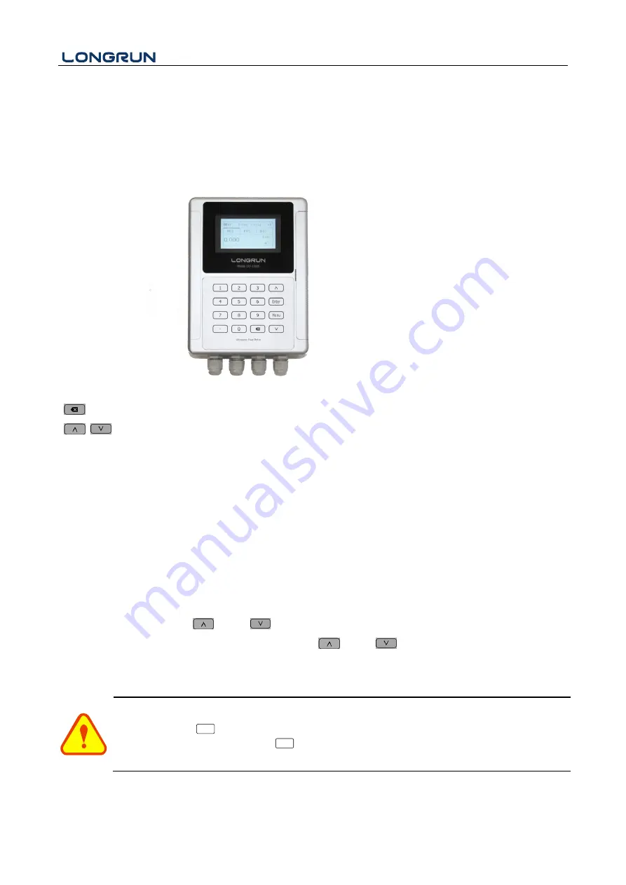
The flow meter adopts the window software design to consolidate or subdivide all of the parameters entered, the 
instrument setup and measurement result displays into independent windows. The operator can input parameters, 
modify settings or display measurement results by "visiting" a specific menu window. Each window serial number, 
or so-called window ID code, has a defined meaning. For example, Window M10 indicates the parameter input for 
pipe outside diameter, while Window M14 indicates the mounting spacing between the transducers, etc. (Refer – 
Windows Display Explanations). 

The  keypad  shortcut  to  visit  a  specific  window  is  to  press  the  “  Menu”  key  at  any  time,  then  input  the  2-digit 
window ID code. For example, to input or check the pipe outside diameter, just press the “ Menu” “1” “0” keys 
for window ID code 10. Use “

”and    “

” to switch.


Another method to visit a particular window is to press    “

”and    “

”    to scroll the screen.   

You  can  check  the  corresponding  parameters  by  visiting  the  Data  Type  Windows.  If  you  want  to  modify  the 
parameters, press “ Enter ” first, input the digits then press “ Enter ” again to confirm. 


Attention 

Generally, press 

Enter

  key first if operator wants to enter "modify" status. If the "modify" is still not 

possible  even  after  pressing  the 

Enter

  key,  it  means  that  system  is  locked  by  a  password.  To 

"Unlock" it, select "Unlock" in Window M54 and enter the original password. 

Summary of Contents for LRF-3000S

Page 1: ...LRF 3000S Ultrasonic Transit time Flow meter Revision 1 0 0 UpdateRecord October 2018...

Page 2: ...avoiding the damage to the flow meter or improper use Warning May cause injury Attention May damage the flow meter Some of the instructions may be different to the flow meters you purchased depending...

Page 3: ...9 3 2 Measurement Site Selection 10 4 Transducer Installation 13 4 1 Transducer Installation 13 4 1 1 Transducer Spacing 13 1 1 2 Transducer Mounting Methods 13 4 1 3 V Method 13 4 1 4 Z Method 14 4...

Page 4: ...cations Protocol 46 8 1 Overview 46 8 2 Serial port definitions 46 8 3 Direct connection via RS232 to the host device 47 8 4 Communications protocol and the use 47 8 4 1 HL Protocol 47 8 4 2 MODBUS I...

Page 5: ...ess output signals etc can be conveniently entered via the windows British and Metric measurement units are available 3 Daily monthly and yearly totalized flow Totalized flow for the last 64 days and...

Page 6: ...stable Relay output max Frequency 1Hz 1A 125VAC or 2A 30VDC Communication Interface RS232 RS485 SD Card Option Max record 512 days Record time interval 1 3600 s Power Supply 10 36 VDC AC90 245V Keypad...

Page 7: ...has been installed the flow meter wiring can be connected Open the case you will find the Power board wiring ports from left to right are as follows Connect to power supplier Relay Output OCT Output T...

Page 8: ...meter is switched on the system will run automatically according to the last input parameters If the installation is accomplished when system is switched on gain adjustment can be monitored in Window...

Page 9: ...code has a defined meaning For example Window M10 indicates the parameter input for pipe outside diameter while Window M14 indicates the mounting spacing between the transducers etc Refer Windows Disp...

Page 10: ...ind M10 enter the pipe size the outer diameter of the pipe and the pipe thickness Press the Enter to confirm OD 200 0 mm M10 Pipe settings R Size M thk 4 0 mm Step2 Pipe Material Use to switch to sele...

Page 11: ...selected mounting method M14 INSTL Spacing R Value 154 2 mm Step 7 Display Measurement Results Menu 01 will display flow rate Subject to the real measurement M01 Flow Rate R Flow Vel 100 2 m3 h 3 2 M...

Page 12: ...s installation On the horizontal pipe the transducer should be mounted on the 9 and 3 of the pipe avoiding the position of 6 and 12 in case of the signal attenuation caused by pipe at the bottom sedim...

Page 13: ...LRF 3000S Ultrasonic Transit time Flow meter 12...

Page 14: ...he top portion of the pipe Refer to Transducer Mounting If the transducers cannot be mounted horizontally symmetrically due to limitation of the local installation conditions it may be necessary to mo...

Page 15: ...s is because the Z method utilizes a directly transmitted rather than reflected signaling which transverses the liquid only once The Z method is able to measure on pipe diameters ranging from 100mm to...

Page 16: ...sted and the pipe should be re inspected If necessary change the mounting method to be Z method 4 2 2 Signal Quality Q value Q value is short for Signal Quality displayed in Window M04 It indicates th...

Page 17: ...ignal detected Thus it is necessary to check that the parameters including all the pipe parameters have been entered accurately Check to be sure the transducer mounting method has been selected proper...

Page 18: ...Zero is too big that indicates the quality of the instrument is poor If the zero set point is not at true zero flow a measurement difference may occur The smaller the physical measurement capacity is...

Page 19: ...perL When flow direction is an issue module 0 4 20mA is available When the flow direction displays as negative the current output is in range of 0 4mA whereas the 4 20mA is for the positive direction...

Page 20: ...he flow ranges using the software alarm system There are two software alarms Alarm 1 and Alarm 2 Example 1 When flow rate exceeds 300 1000 m3 h in order to program the relay output alarm Complete the...

Page 21: ...tive totalizer Data storage format a 2017 11 16 16 21 12 b 2 652471E 00 m3 h c 9 380460E 02 m s d 3 520580E 02 m3 e 3 520580E 02 m3 f 0 000000E 00 m3 g 0 000000E 00 GJ h h 0 000000E 00 GJ i 0 000000E...

Page 22: ...to view in Window M50 ATTENTION Other Operating Refer to 6 2 Window Display Explanations Attention Do not remove the SD card from the reader while actively working with the data Data should be saved a...

Page 23: ...M01 Flow Rate M02 Hot M03 Cool M04 Status M1X Installation Setting M10 Pipe Settings M11 Lining Settings M12 Liquid Settings M13 Transducer Settings M14 Installation Space M2X Calibration Setting M20...

Page 24: ...on M4X Flow Unit Opinions M40 Toggle Units M41 Flow Units M42 Energy Units M43 Temperature Units M5X System Settings M50 Serial Number M51 Time and Date M52 Key Ton M53 Language M54 System Lock M55 Sy...

Page 25: ...e totalizer Use and to switch M01 Flow Rate Display the Flow Rate and Flow Total Display the Velocity Flow Rate and the Flow Total switch every 6 seconds Use the ENTER to stop the switch M02 M00 Flow...

Page 26: ...witch every 6 seconds Use the ENTER to stop the switch M03 Cool Rate Display the Cool Total Display the Cool Rate and the Inlet Water Temp and Outlet Water Temp NOTE Instrument needs energy capacity x...

Page 27: ...should be 100 3 If the difference is too large the user should check that the parameters are entered correctly especially the sound velocity of the fluid and the installation of the transducers This...

Page 28: ...Iron Pipe 5 Copper 6 Alu Aluminum pipe 7 ACP Asbestos Cement Pipe 8 FPG Fiberglass Pipe 9 Other It is possible to enter other materials which are not included in previous eight items Once item 9 is s...

Page 29: ...l 6 PS Polystyrene 7 Polyester 8 PE Polyethylene 9 Ebonite 10 Teflon 11 Other Item 11 Other is available to enter other materials that are not included in previous ten items Once the Other is selected...

Page 30: ...ct method 2 N M14 Installation space This value is calculated by the flow meter The operator must mount the transducer according to the transducer spacing displayed ensure that the transducer spacing...

Page 31: ...ue is called Zero Point When Zero Point is not at zero in the flow meter the difference is going to be added into the actual flow values and measurement differences will occur in the flow meter Set ze...

Page 32: ...ch M23 Totalizer Select the totalizer type 0 POS Positive Totalizer 1 NEG Negative Totalizer 2 NET Select energy type 0 Heat 1 Cool Select ON OFF to switch the totalizer Select the flow totalizer valu...

Page 33: ...the function of power down automation correction switch the flow lost in an offline session can be estimated and automatically adjusted The estimate is based on the average value which is obtained fr...

Page 34: ...Open the Sectional Correction Function OFF Close the Sectional Correction Function Delay correction Engineer menu suggest customer use the factory setting TPC Transducers power control Engineer menu...

Page 35: ...9600 None 3 19200 None 4 38400 None 5 56000 None M31 AI Setting Display analog input AI1 analog value Display analog input AI2 analog value M28 SQA R Option 0 ON 1 OFF Set Value 4 500 Reset M28 SQA R...

Page 36: ...0MA Set the CL output value according to the flow value at 20mA 4 20mA check opinions a Check 4mA b Check 8mA c Check 12mA d Check 20mA M33 OCT Setting LowerL 1 0 UpperL 1000 0 M31 AI Settings R AI1 A...

Page 37: ...h Rationing i Uart CTRL Select the OCT Range value OCT check opinions a Check 500 b Check 1000 c Check 3000 d Check 5000 M34 Relay Setting The following signal options are available Option a Flow Rate...

Page 38: ...than the low value will activate the alarm in the OCT hardware or relay output signal Enter the Upper alarm value any of the measured flow which is higher than the high value will activate the alarm...

Page 39: ...ption M40 Toggle Unit Select the measurement unit as follows a Metric b British M41 Flow Unit The following flow rate units are available 0 Cubic Meters m3 1 Liters 1 2 USA Gallons GAL 3 Imperial Gall...

Page 40: ...Energy Unit The following Energy units are available 0 Giga Joule GJ 1 Kilocalorie Kc 2 MBtu 3 KJ 4 Btu 5 KWh 6 MWh 7 TH a x 0 001 E 3 b x 0 01 E 2 c x 0 1 E 1 d x 1 E 0 e x 10 E 1 f x 100 E 2 g x 10...

Page 41: ...uses it for files setup and for management by the user SVN is the software version M51 Time and Data Date and time modifications are made in this menu M52 Key Tone Use this menu to ON OFF the key ton...

Page 42: ...System Reset Select 1 Reset to make the instrument back to factory M60 Date Totalizer The following options are available 0 Day 1 Month 2 Year In this window it is possible to review the historical f...

Page 43: ...he pass word to adjust M64 RTD Adjust This menu is for the AI calibration enter the pass word to adjust Value 5 Day M61 Running Time R 4mA Enter to go 20mA Enter to go M62 CL Adjust R 0 C Enter to go...

Page 44: ...LRF 3000S Ultrasonic Transit time Flow meter 43 AI1 AI2 M64 AI adjust R 20mA Enter to go 4mA Enter to go AI1 AI2 M64 AI adjust R 20mA Enter to go 4mA Enter to go...

Page 45: ...entative for assistance 7 1 Table 1 Error Codes and Solutions during operation Codes The upper right corner of the screen Causes Solutions R System Normal System normal E Signal Not Detected Signal no...

Page 46: ...ly Slowly and slightly move each transducer with respect to each other around the installation point until the maximum signal is detected Be careful that the new installation location is free of scale...

Page 47: ...length 0 1000m can be directly used for data transmission links for a short distance Current loop can be used in medium or long distance transmission When the flow meter is used in a network environm...

Page 48: ...baud rate of asynchronous communication Primary station computer system Secondary station ultrasonic flow meter is generally 9600BPS A single byte data format 10 bits one start bit one stop bit and 8...

Page 49: ...Return Relay Status ON OFF cr RDT cr lf Current date and time yy mm dd hh mm ss cr RSN cr lf Return serial number dddddddt cr Note 4 SFQdddd d cr lf OCT setting dddd d cr Successful setting will back...

Page 50: ...and P commands can be used in combination for example W123PRT which means that the instrument that reads the network address is the cumulative value of the instrument with 123 and its return data has...

Page 51: ...s at the beginning while the high byte is at the end For example to read the address 1 0x01 in the RTU mode if the instantaneous flow rate uses hour as a unit m3 h namely reads 40005 and 40006 registe...

Page 52: ...code is 0x01 0x83 0x02 0xC0 0xF1 Flow meter Address Error Code Error Extended Code CRC Verify Code 5 MODBUS Register Address List The flow meter MODBUS Register has a read register and a write single...

Page 53: ...l hot exponent 16 bits int 1 0016 40023 Energy total cold high word 32 bits real 2 0017 40024 Energy total cold exponent 0018 40025 Energy total cold exponent 16 bits int 1 0019 40026 Up signal int lo...

Page 54: ...l number char 7 8 0049 40074 Analog Input AI1 Value low word 32 bits real 2 Returned temperature value with RTD option 004a 40075 Analog Input AI1 Value high word 004b 40076 Analog Input AI2 Value low...

Page 55: ...5 cf Cubic Feet 6 ba US Barrels 7 ib Imperial Barrels 8 ob Oil Barrels 2 The following energy units are available 0 GJ Giga Joule 1 Kc Kilocalorie 2 MB MBtu 3 KJ Kilojoule 4 Bt Btu 5 Ts US Tonnes 6 T...

Page 56: ...d Pipe Material Sound Velocity m s Steel 3206 ABS 2286 Aluminum 3048 Brass 2270 Cast iron 2460 Bronze 2270 Fiber glass epoxy 3430 Glass 3276 Polyethylene 1950 PVC 2540 Liner Material Sound Velocity Te...

Page 57: ...0 1554 4 13 1458 7 47 1538 9 81 1554 2 14 1462 3 48 1540 2 82 1553 9 15 1465 8 49 1541 3 83 1553 6 16 1469 3 50 1542 5 84 1553 2 17 1472 7 51 1543 5 85 1552 8 18 1476 0 52 1544 6 86 1552 4 19 1479 1 5...

Page 58: ...sit time Flow meter 57 Longrun Industrial Instrument Co Ltd 24hours service 86 186 5435 6933 Tel 86 543 3382666 Fax 86 543 3615999 E mail info ultrasonicscn com Website www longrun flowmeter com This...

Reviews: