


To synchronise a remote control to a machine, follow these
instructions:
1) Ensure the welding power supply is switched off.
2) Press and hold the parameter select/adjust knob on the front panel of the
power supply (2-4 seconds) while at the same time turning the machine ON
using the ON-OFF switch on the back of the welding power supply.
3) When the display on the front panel of the power supply is blank, release the
control knob. Turn on the remote control or foot pedal while at the same time
pressing any buttons on the remote control panel or foot pedal, the digital
meter on the front panel of the welding power supply flick twice to indicate the
synchronization is successful and complete.( Synchronization has to accomplish
in 10s after the display is blank.)
4) Switch the machine off and back on again to start welding operation.
5) If the operation is unsuccessful, repeat steps 1 to 4.
6) During operation, the front panel control on the power supply is still functional
but the remote control panel or foot pedal has higher priority level.
7) When the remote control panel or foot pedal is idles for 10 seconds, it will
automatically go into “sleep” mode.
8) Only front Panel Control is active when wireless remote control or foot pedal is in
“sleep” mode. Any operation on the wireless remote control panel or foot pedal
will “wake it up and resumes control of the machine.
How to remove the control function of Remote control box on
welding machine
1) Ensure the welding power supply is switched off.
2) Press the encoder on the front control panel of the power supply, meanwhile
turn on the machine.
3) Pressing the encoder about 10 seconds, until the control panel display "rSt",
then it succeed.
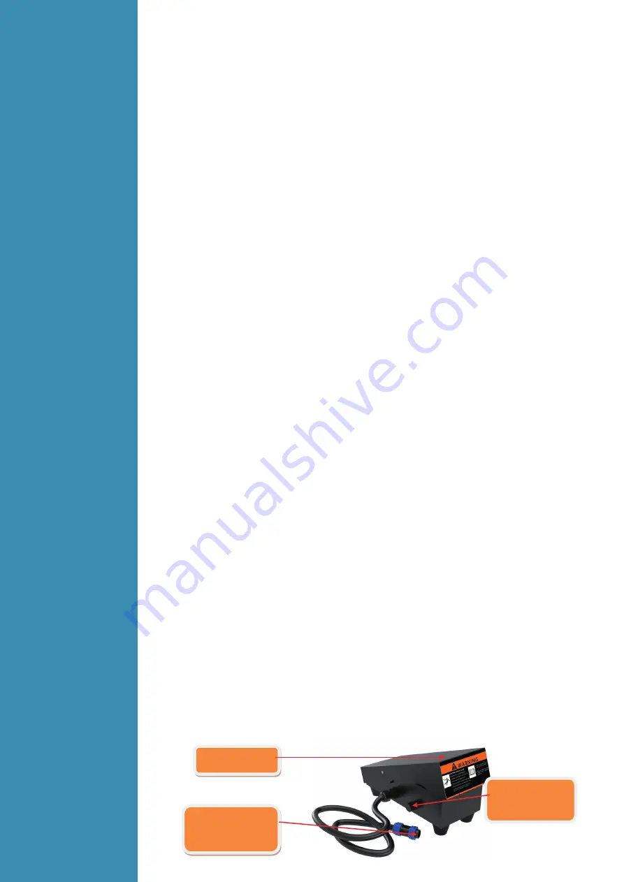
3.5.2
Wire foot
pedal
Configura-
tion
● When plug the twelve-lead aero-socket of pedal switch in it. Welder will identify
the pedal switch, the welding current knob on the front panel will can’t use
,
and only 2T can be selected.
● When use the adjustment knob of max-welding current beside the pedal,can
set the max-current you want.
Connected to the
12 pin aero socket
on the front panel
Adjustment knob
of welding current
Adjustment knob of
max welding
current
current


