LOKERMANN GRAND MIG 315 COMPACT User Manual Download Page 12

4.3.4 

MIG Torch 

Liner Types 

and 

Information

MIG Torch Liners

The liner is both one of the simplest and most important components of a MIG gun. Its sole purpose is 

to guide the welding wire from the wire feeder, through the gun cable and up to the contact tip.

Steel Liners

Most MIG gun liners are made from coiled steel wire also known as piano wire, which provides the 

liner with good rigidity and flexibility and allows it to guide the welding wire smoothly through the 

welding cable as it bends and flex during operational use. Steel liners are primarily used for feeding

of solid steel wires, other wires such as Aluminium, Silicon Bronze etc will perform better using a teflon 

or Polyamide line. The internal diameter of the liner is important and releative to the wire diameter 

being used and will assit in smooth feeding and prevention of the wire kinking and birdnesting at the 

drive rollers. Also bending the cable too tightly during welding increases the friction between the 

liner and the welding wire making it more difficult to push the wire through the liner resulting in poor 

wire feeding, prematureliner wear and birdnesting. Dust, grime and metal particles can accumalate

inside the liner over time and cause friction and blockages, it is recommended to periodically blow 

out the liner with compressed air. Small diameter welding wires, 0.6mm through 1.0mm have 

relatively low columnar strength, and if matched  with an oversized liner, can cause the wire to 

wander or drift within the liner. This in turn leads to poor wire feeding and premature liner failure due 

to excessive wear. By contrast, larger diameter welding wires, 1.2mm through 2.4mm have much 

higher columnar strength but it is important to make sure the liner has enough internal diameter

clearance. Most manufacturers will produce liners sized to match wire diameters and length of 

welding torch cable and most are colour coded to suit.

4.3.5 

MIG 

Welding

Definition of MIG Welding 

MIG (metal inert gas) welding also known as GMAW (gas metal arc welding) or MAG (metal active 

gas welding), is a semi-automatic or automatic arc welding process in which a continuous and 

consumable wire electrode and a shielding gas are fed through a welding gun. A constant voltage,

direct current power source is most commonly used with MIG welding. There are four primary 

methods of metal transfer in MIG welding, called short circuit (also known as dip transfer) globular 

transfer, spray transfer and pulsed-spray, each of which has distinct properties and corresponding 

advantages and limitations. To perform MIG welding, the basic necessary equipment is a welding 

gun, a wire feed unit, a welding power supply, an electrode wire, and a shielding gas supply. Short

circuit transfer is the most common used method whereby the wire electrode is fed continuously 

down the welding torch through to and exiting the contact tip. The wire touches the work piece and 

causes a short circuit the wire heats up and begins to form a molten bead, the bead separates from 

the end of the wire and forms a droplet that is transferred into the weld pool. This process is repeated 

about 100 times per second, making the arc appear constant to the human eye.

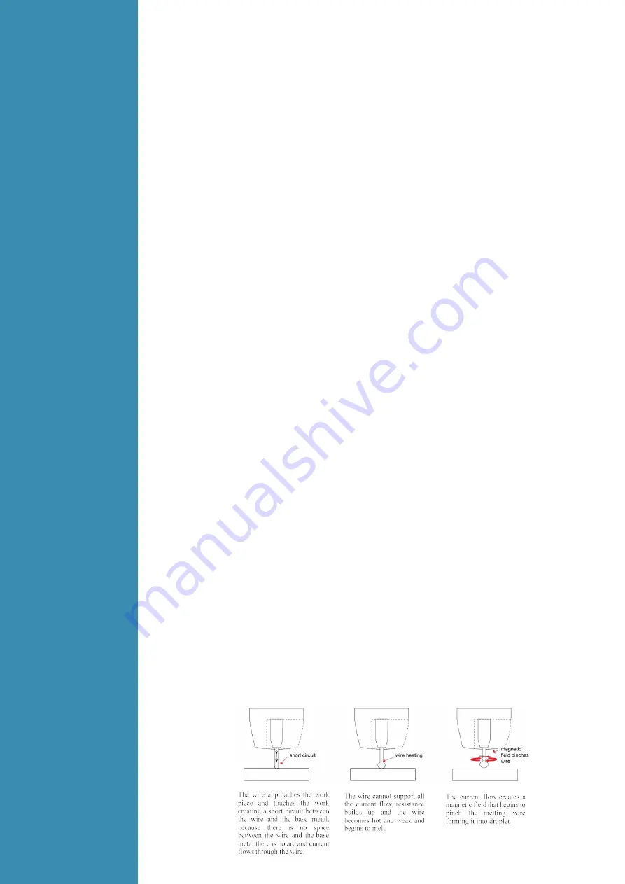
Short Circuit Transfer

 - Short circuit transfer is the most common used method whereby the wire 

electrode is fed continuously down the welding torch through to and exiting the contact tip. The wire 

touches the work piece and causes a short circuit the  wire heats up and begins to form a molten 

bead, the bead separates from the end of the wire and forms a droplet that is transferred into the 

weld pool. This process is repeated about 100 times per second, making the arc appear constant 

to the human eye.

Basic MIG Welding


Summary of Contents for GRAND MIG 315 COMPACT

Page 1: ...IMPORTANT Read this OPERATOR MANUAL together with PRESCRIPTION AND COMPLIANCE MANUAL before to use this equipment In case of loss one of two parts contact immediately your dealer Allow the operator t...

Page 2: ...4 1 Layout for the front and rear panel 4 2 Wire Feeder of welding machine 4 3 Welding operation 4 3 1 Wire Feed Roller Selection 4 3 2 Wire Installation and Set Up Guide 4 3 3 MIG Torch Liner Instal...

Page 3: ...ring of the public supply system Consideration should be given to shielding the supply cable of permanently installed arc welding equipment in metallic conduit or equivalent Shielding should be electr...

Page 4: ...5 COMPACT Features 1 Digital control system real time display the welding parameters 2 High performance power source MIG MAG 3 Waveform control stable welding arc 4 IGBT technology low power consumpti...

Page 5: ...The relation between the rated loading voltage and welding current 3 Installation and Adjustment 3 1 Parameters Models Parameters GRAND MIG 315 COMPACT Input Voltage V 3 380 400 440 10 Frequency HZ 5...

Page 6: ...ut current or the duty cycle should be reduced 3 3 Equipment Connection 1 Insert the earth cable plug into the negative socket on the front of the machine and tighten it 2 Plug the welding torch into...

Page 7: ...ne end of the guide Tighten the wire guide in place with the mounting nut Cut the wire guide 2mm from the mounting nut and file the sharp edges of the cut round Reattach the gun in place and tighten t...

Page 8: ...en the wire speed LED is on 10 Current display Welding Current display when machine is working Set current display before welding Unit A 11 Voltage display Welding voltage display when machine is work...

Page 9: ...t screw the contact tip into the tip holder of the torch head and nip it up tightly 7 Fit the gas nozzle to the torch head 8 Carefully open the gas cylinder valve and set the required gas flow rate 9...

Page 10: ...bend easily and is therefore more difficult to feed Soft wires can easily buckle at the wire feeder where the wire is fed into inlet guide tube of the torch The U shaped roller offers more surface ar...

Page 11: ...rrect drive tension is to bend the end of the wire over hold it about 100mm from your hand and let it run into your hand it should coil round in your hand without stopping and slipping at the drive ro...

Page 12: ...al diameter clearance Most manufacturers will produce liners sized to match wire diameters and length of welding torch cable and most are colour coded to suit 4 3 5 MIG Welding Definition of MIG Weldi...

Page 13: ...r travel speeds providing a flatter weld profile with light penetration useful for welding thin materials The welds are wider and flatter allowing for minimal clean up grinding time Perpendicular Tech...

Page 14: ...d pool produce spatter and over heat the contact tip Too long stick out will cause an unstable arc lack of penetration lack of fusion and increase spatter Travel Speed Travel speed is the rate that th...

Page 15: ...producing a weld deposit of good quality Gas selection The purpose of the gas in the MIG process is to protect shield the wire the arc and the molten weld metal from the atmosphere Most metals when he...

Page 16: ...g MM Gas flow rate L MIN Butt joint 1 6 1 0 80 100 19 21 40 50 12 15 10 15 2 0 1 0 90 100 19 21 40 50 13 16 13 15 3 2 1 2 150 170 22 25 40 50 14 17 15 17 4 5 1 2 150 180 24 26 30 40 14 17 15 17 6 0 1...

Page 17: ...arc in unprotected eyes Ensure good ventilation of the machine to improve Duty Cycle Turn off the engine when the operation finished for energy consumption efficiency When power switch shuts off prote...

Page 18: ...ches in the front and at the back of arc welding machine are flexible and put correctly in place If any knob has not been put correctly in place please correct If you can t correct or fix the knob ple...

Page 19: ...protection always on Welding machine E10 Phase loss Yellow lamp thermal protection always on E12 No gas Red lamp always on E13 Under voltage Yellow lamp thermal protection always on E14 Over voltage...

Page 20: ...LOKERMANN Srl Via Produzione 16 18 37044 Cologna Veneta VR Italy Tel 39 0442 1722469 lokermann lokermann eu www lokermann eu...

Reviews: