background image

23


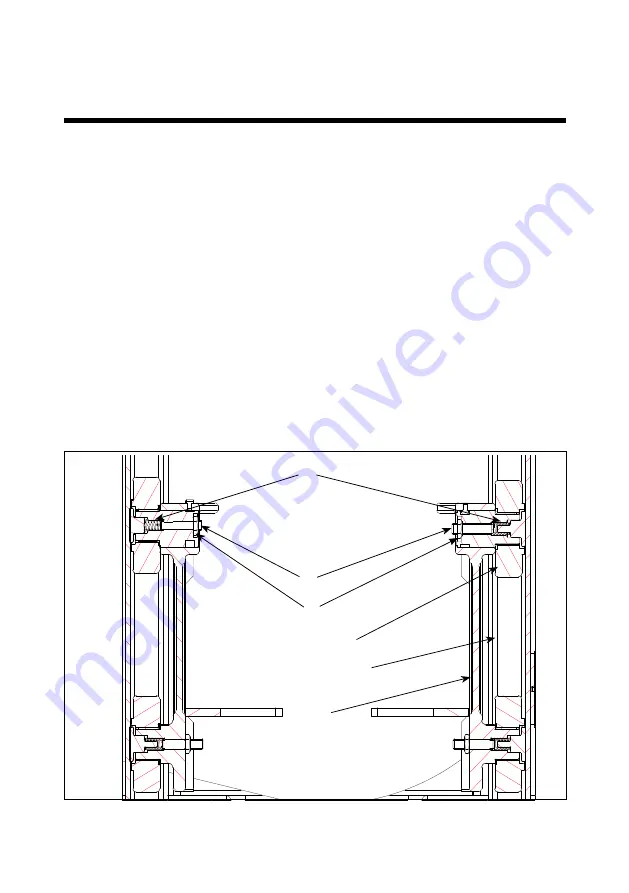
A

C

B

C-profile (mast)

Mast roll

Carriage

6.6 Adjustment of side play

1.  Screw (A) is loosened counter-clockwise, until resistance disappears.
2.  Turn the screw clockwise, until resistance appears. The following 1.5 to 2.5 

turns of the screw will be a tightening of the spring (C).

3.  When a larger resistance appears, make 0.25 turn counterclockwise, and the 

counter nut (B) will be tightened.

4.  Lift the carriage to the top position, and when lowering it has to slide to the 

bottom. If this is not the case, loosen screw A, make c. 0.5 turn counter-

clockwise and repeat point 4.

6.0 Long live the Logiflex

Summary of Contents for LOGIFLEX SELF1003

Page 1: ...LOGIFLEX SELF1003 SELFS1003...

Page 2: ...r Serial no a has been manufactured in conformance with the stipulations of the Directive no 2006 42 EC Directive no 2014 30 EC Directive no 2014 35 EC b has been manufactured in conformance with the...

Page 3: ...4 Avoid overloads 16 4 5 Emergency stop 17 4 6 Personal safety 17 5 0 There must be a current supply 18 5 1 Fuses replacement 18 5 2 Wirring connections 18 6 0 Long live the Logiflex 19 6 1 Lubricatio...

Page 4: ...duct Risks with improper use The fully powered Logiflex is manufactured in accordance with safety directives Among the subjects dealt with in this Instruction Manual are Therefore please read this Ins...

Page 5: ...Safety Switch 2 Horn 3 Lift Lower 4 Forward Reverse 5 Multiflex Function 6 Handle 7 Battery indicator hour counter 8 Emergency Stop 9 Ignition Key 10 Name plate serial number 11 Charging Lamp 2 0 Fun...

Page 6: ...forks will lift 190 mm before the telescopic mast begins to extend SELF1003 2050 3300 SELFS1003 2020 3270 3 1 Handling of pallets For proper operation stand behind the handle 3 0 How to operate the Lo...

Page 7: ...7 SELF1003 SELFS1003 When handling closed pallets use stacker with straddle legs 3 0 How to operate the Logiflex...

Page 8: ...of the handle Position A Drive position Drive current on Brake deactivated Position B Stop Brake Emergency Stop Drive current off Brake activated Note Emergency stop 2 must not be activated 3 2 Use o...

Page 9: ...9 3 0 How to operate the Logiflex...

Page 10: ...the stacker even though the handle is in its upright braked position The function requires two handed operation i e it must be performed deliberately The function facilitates manoeuvring in confined...

Page 11: ...safety switch on the end of the handle ensures that the operator cannot be trapped when the stacker is reversed When the safety switch is activated the stacker will change direction and move forwards...

Page 12: ...hours the hours the hydraulic pump has been in operation Under normal operation the TOTAL hours are displayed in the lower 6 digit field If the Forward Reverse switch is activated shortly the TRAC hou...

Page 13: ...lt number is showed in the upper 3 digit field See point 7 1 for Fault code description 3 4 4 State of operation LED s The LED s indicate the state of operation Green Normal operation Yellow Warning s...

Page 14: ...s shall be raised as little as possible Transport with raised forks should be made over the shortest possible distances and at low speed Do not exceed the permitted capacity of the product Check that...

Page 15: ...capacity is set on the safety valve of the product Specific to Logiflex with load limitation at significant lifting heights The fork bracket loading is dependent on the lifting height and can be read...

Page 16: ...and level floor During transport the forks shall be raised as little as possible Transport with raised forks should be made over the shortest possible distances and at low speed 4 4 Avoid overloads Th...

Page 17: ...in current supply is switched off The movement of the forks stops immediately Driving with the truck stops immediately The emergency stop is deactivated by turning the switch to the right 4 6 Personal...

Page 18: ...The old fuse is to be removed and replaced by a new one of the same size Find out why the fuses blow 5 2 Wirring connections Many operational disturbances are caused by bad connections in the electric...

Page 19: ...e adjusted and exchanged continuously 6 1 Lubrication and hydraulic oil Under normal operation conditions the stacker requires no lubrication All ball bearings are sealed and lubricated for life and m...

Page 20: ...union in the bottom of the cylinder Activate the hydraulic pump by pressure on the switch The oil will run out 3 Take off the side plates 4 Take off the cables of the battery Remove from the battery b...

Page 21: ...eding the hydraulic system With a load of 50 100 kg the forks must be raised and lowered to top and bottom position 2 3 times 6 4 Fork adjustment Two of the rollers on the fork bracket are mounted on...

Page 22: ...ng movement has to stop in the cylinder before the mast rolls touch the top stop After adjusting please check a Fork bracket the forks have to be placed above the wheels b Adjustable carriage the fork...

Page 23: ...e following 1 5 to 2 5 turns of the screw will be a tightening of the spring C 3 When a larger resistance appears make 0 25 turn counterclockwise and the counter nut B will be tightened 4 Lift the car...

Page 24: ...ed out and the life of the equipment shortened Avoid spraying directly with liquids on the handle and other electrical components Cleaning of the plastic screen polycarbonate The screen is to be washe...

Page 25: ...low Power supply is missing Charge battery Check fuses 16 22 Controller overheated Contact the dealer 39 Error main relais Contact the dealer For other error codes contact your dealer 7 1 Fault codes...

Page 26: ...not lift when UP is pressed G No click can be heard when UP is pressed H Forks lift only a little not to max height when UP is pressed I Forks do not sink when DOWN is pressed J Forks sink slowly K Th...

Page 27: ...ry discharged Fault in on off switch Fault in control current circuit Fault in main power current circuit Too little current on battery No current on brake Brake needs adjusting Insufficient oil in ta...

Page 28: ...can be found and the stacker does not drive contact the dealer 6 Check battery see point 2 above 7 Check the wheel motor The wire connection for the brake is checked These must be connected If no faul...

Page 29: ...29 7 0 Fault codes Fault location key...

Page 30: ...your Logitrans dealer carriage paid within the warranty period in force at the time in question together with a copy of the documentation for the service performed B0284 see the back page The warrant...

Page 31: ...31...

Page 32: ...500 hours of operation Safety inspection should be performed by the dealer or other qualified persons at least once each year unless local regulations state otherwise The inspections are to be perform...

Reviews: