logitrans HS 1000RF-SEMI Manual Download Page 16

16

6.0 Good service after purchase

6.1 Ordering spare parts

The correct spare parts are obtainable from your dealer. 

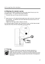
When ordering, please state: 

•   Serial number of the product

•   Type and width/length of the product

• 

 Spare part no.  Please find spare part no. on 

www. logitrans.com

.

6.2 Warranty/Compensation

Spare parts delivered during the warranty period will be invoiced. A credit note 

will be sent immediately after we have received and tested the defective parts 

and found that the warranty conditions have been met. 

6.3 Service and repair

You should be able to make adjustments and perform minor repairs on the 

spot. However, major repairs should be left to the dealer who has well-trained 

personnel and the necessary special tools. 

6.4 Warranty

The warranty covers material and assembly defects which, subject to inspection by 

us or our representative, are deemed to be faults or deficiencies that prevent normal 

use of the parts concerned. Such affected parts shall be sent to your  

Logitrans dealer carriage paid within the warranty period in force at the time in 

question, together with a copy of the documentation for the service performed 

(B284 - see the back page). The warranty does not cover normal wear and  

adjustments. 

The warranty period is based on singleshift working.

The warranty shall no longer apply if

•   the product has been used incorrectly,

•   the product is used in environments for which it was not designed,

•   the product has been overloaded,

•   replacements of parts have been made incorrectly or original parts have not 

been used and consequential damages have arisen,

•   if the product is changed or accessories, not being approved by Logitrans, 

are used.

• 

 it can not be proved that a qualified technician has performed the service 

check according to the requirements stated in the instruction manual (see the 

back page).

6.5 Liability exemption

The manufacturer accepts no responsibility for personal injury or material damage 

arising from deficiencies, defects or improper usage. The manufacturer accepts 

no responsibility for lost earnings, operating losses, lost time, lost profits or similar 

indirect losses incurred by the purchaser or a third party.

Summary of Contents for HS 1000RF-SEMI

Page 1: ...HS 1000RF SEMI ...

Page 2: ...Type HS 1000RF SEMI HSS 1000RF SEMI Year of manufacture Serial No a Has been manufactured in conformance with the stipulations of the Directive no 2006 42 EC b Has been manufactured in conformance with the stipulations of the standard EN 3691 5 Name Gitte K Berg Position CEO Company Logitrans A S Product type declaration of Signature 10 10 2016 Distributor ...

Page 3: ...ance with safety directives Among the subjects dealt with in this Instruction Manual are Therefore please read this Instruction Manual carefully 1 0 Before the first lift Proper application Physical limitations of the product Risks with improper use ...

Page 4: ...4 HS RF SEMI For proper operation stand behind the handle Push pull pump 2 0 How to operate the stacker 2 1 Handling of pallets ...

Page 5: ...5 2 2 The three release lever positions 1 Quick Lift 2 Normal Lift 3 Lowering 2 2 1 Quick Lift 0 ca 300 kg 2 2 2 Normal Lift ca 300 1000 kg 2 2 3 Lowering 2 0 How to operate the stacker ...

Page 6: ...ease the risk of toppling Goods on pallets etc must be properly secured so that they cannot fall off during transport when the truck is lifted or when the truck must remain lifted for a time 3 3 Safety valve pressure relief valve The pressure relief valve on the stacker is factory set for the maximum design load 1000 kg The setting protects the truck from overload so that it cannot be damaged by t...

Page 7: ... pull the release lever up to lower the load to the ground The stacker is designed for use on even and level floor During transport the forks shall be raised as little as possible Transport with raised forks should be made over the shortest possible distances and at low speed 3 5 Emergency braking 3 0 Optimum safety ...

Page 8: ...ring transport the forks shall be raised as little as possible Transport with raised forks should be made over the shortest possible distances and at low speed Check that the chains lift equally They shall be equally tight when the forks are loaded Chains and chain bolts must not be damaged Chains that have become permanently stretched max 2 of original length must be scrapped ATTENTION Moving par...

Page 9: ...ood industry The hydraulic system is filled with hydraulic oil of viscosity class ISO VG 15 and viscosity index 372 The oil is suited for use in the temperature range 40ºC to 50ºC The hydraulic oil must be changed every second year 4 2 Oil change Draining the oil Bring the forks down to the lowest position Tip the truck over on its side and remove the plug No 120 Oil now runs out of the filling ho...

Page 10: ...acement instructions accompany the replacement part Therefore order before replacing After replacement adjust the oil quantity in the tank as described under Oil change point 4 2 Then bleed the system pkt 4 6 4 4 Seal leakage Locate the point at which oil leakage appears and then replace defective seals See spare parts list 4 5 Valve cone does not seal completely Pump quickly a few times so that o...

Page 11: ...n when screw no 130 has been loosened Tighten the screw again before raising the handle If the hydraulic system contains only a small amount of air it will be bled automati cally when the forks with load are pumped up to top position 4 7 Cleaning The product should not be cleaned with cleaning materials too frequently as this can lead to corrosion on the galvanised parts When cleaning the stacker ...

Page 12: ...ering mechanism is adjusted correctly if Quick lift when the release lever is in bottom position Normal lift when the locking pawl of the release lever is If this is not the case adjust as follows 1 Place the release lever in normal position locking pawl engaged 2 Press the handle down pos P 3 Tighten in this position the nut pos 113 as much as possible without the forks beginning to move down 4 0...

Page 13: ...s 4 11 Marking The mast lifting capacity and the corresponding centre of gravity distance are given by the pictogram on the side of the mast The lifting capacity of the mast is the same as the max lifting capacity of the product Max lifting capacity is set on the safety valve in the pro duct 4 12 Warranty Stain or tarnishing on the stacker because of the environment in which it is used or the way ...

Page 14: ...h the handle in its normal position The forks do not lift quickly when the handle is in its Quick position Forks cannot be lowered The forks sink after they have been raised The forks cannot be raised by repeated pumping attempts Forks do not raise at the first pump stroke or the pump do not operate in the whole pump stroke Pump does not react when changing over the release lever sluggishness Fork...

Page 15: ...lease pin jammed in control valve Air in hydraulic Low temperature Degrees below freezing point Mast needs adjustment Pressure relief valve See point 3 3 See point 4 1 See point 4 3 See point 4 4 See point 4 5 See point 4 6 See point 4 1 See point 4 9 4 10 See point 4 3 See point 4 8 Exchange rub ber pin If neces sary the whole valve insert See point 4 3 Lowering mechanism needs adjustment If the ...

Page 16: ... your Logitrans dealer carriage paid within the warranty period in force at the time in question together with a copy of the documentation for the service performed B284 see the back page The warranty does not cover normal wear and adjustments The warranty period is based on singleshift working The warranty shall no longer apply if the product has been used incorrectly the product is used in envir...

Page 17: ...17 ...

Page 18: ...18 ...

Page 19: ...19 ...

Page 20: ...be performed on the basis of form no B278 and proved on form no B284 Forms and instructions for the safety inspection are available at your dealer Periodic service check Service check is required once each year or at least for every 250 hours of operation The service check is to be performed on the basis of form no B280 and proved on form no B284 Forms and instructions for the service check are av...

Reviews: