

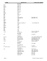

SYMBOL
DESCRIPTION
LOGITEK PART NUMBER
Page 7
** MON-10 Instruction Manual **
Resistors
R1-4
69.8K, 1%
R5-8
4220, 1%
R9-12
69.8K, 1%
R13-16
4220, 1%
R17
6810, 1%
R18
1540, 1%
R19
909, 1%
R20
562, 1%
R21
174, 1%
R22
53.6, 1%
R23,24
5100
R25
560
R26
11.5K, 1%
R27
5100
R28
1M
R29
5000 peak trim
BN-3386P-1-502
R30
10K meter trim
BN-3386P-1-103
R31
1000
R32,33
20K
R34,
1000
R35
10K
R36,37
10
R38a,b
10K ohm VOLUME pot
CL-70W1N04S103A
R39
1000
R40
10K
R41,42
10
R43
1000
R44,45
10K
R46
1000
R47
1.2
R48
10K
R49
150
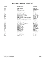
1 pc.
Knob
SO-S211-250BLACK
1 pc.
Cap with line
SO-C211BLACK
Rectifiers
RT1
1A bridge
GI-DF10M
Switches
S(1-10)
Input selector
EC-10XTA15(NONE)4UGRA
S11
Meter selector
GR-71BDF30-01-1-AJN
S12
Source selector
GR-71BDF30-02-1-AJN
10 pc.
Pushbutton cap
SH-FA20108010112
2 pc.
Knob
SO-S211-250BLACK
2 pc.
Cap with line
SO-C211BLACK
Speakers
SP1
Speaker
IC-S300SA
Transformers
T1
36v 1A
ST-P8671
T1 (220V version)
36V 1.2A 220V primary
SI-A41-43-36
Terminals
4 pc.
Terminal blocks
RD-3PCV-15
Label strip
AD-4-15230-0030
Label strip holder
AD-4-25357-0020
Label strip window
AD-4-25358-0140
Power cord
BE-17251
Selector card
LG-131B
Terminal card
LG-132A
Amp card
LG-133D


