background image


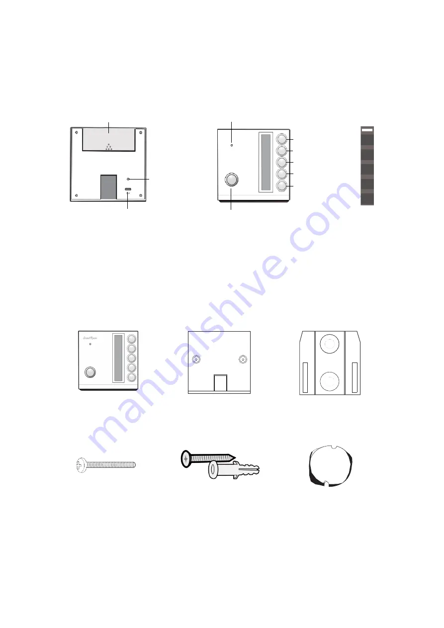
Device Layout 


Packing List 


Multi-Function Button 

Screen Display 

Front 

Back 

System Indicator 

Scene Switch 1 

Scene Switch 2 
Scene Switch 3 
Scene Switch 4 
Scene Switch 5 
Scene Switch 6 

Scene Switch 

Big Base 

Small Base 

M4*30 Screw x2 

Screw/Wall Plug x2 

Screw Plug x1 

Application Indicator 

Battery Compartment 

Summary of Contents for SR-ZRCPBPW-S4160-01

Page 1: ... 2019 Logika Limited Smart Scene Switch SR ZRCPBPW S4160 01 Product Manual Version 1 0 ...

Page 2: ...installation and use Before use the product must be properly installed as described in this manual by a qualified technician The product should be used with the supplied accessories Do not disassemble or modify the product Logika is not responsible for any loss due to improper installation or use of this product Please visit our official website at www logika nz for more information You can also c...

Page 3: ...creen Display Front Back System Indicator Scene Switch 1 Scene Switch 2 Scene Switch 3 Scene Switch 4 Scene Switch 5 Scene Switch 6 Scene Switch Big Base Small Base M4 30 Screw x2 Screw Wall Plug x2 Screw Plug x1 Application Indicator Battery Compartment ...

Page 4: ...led scenes Battery operated and easy to install or use in hand Specifications Communication Protocol IEEE 802 15 4 ZigBee Antenna Configuration PCB Antenna Power DC 3V Battery Type CR2450 2 Stand by Current 1uA Mounting Method Portable Wall Mounted Material Colour PC ABS White Overall Dimension L W 87 86 8 mm Net Weight 78 3g Flame Retardant Rating UL94 V 2 Operating Temperature 10 55 Operating Hu...

Page 5: ...ption A If installing onto a back box use the M4 screws and screw the Big Base onto the back box Option B You can also mount the Big Base directly onto the wall Mark and drill two 5mm holes Insert the wall plugs and screw in the base onto the wall Once the base has been installed insert the CR2450 batteries into the Scene Switch and slot onto the base ...

Page 6: ...efer to the Logika Smart Mobile App user guide which will take you through the process of adding smart devices to the system Refer to the information below to locate the device in the Device Add screen Once selected the app will walk you through how to add the device to the system Device Category Switch Device Name Scene Switch ...

Page 7: ...go out Quit the Zigbee Network Long press the Multi Function Button for 10 seconds The System Indicator light will flash 4 times and go out The device has now been successfully removed from the network and been reset to the factory defaults Binding the Switches Although you can program the Scene Switches from within the app you can optionally bind them direct Only do this if you want to do this bi...

Page 8: ...to connecting the device to the main supply The device must be installed by a qualified electrician Do not disassemble or refit this product or itsaccessories The device should be mounted in a dry environment It is not designed to be used outdoors ...

Page 9: ...s not removed from the test network at the factory Perform the Quit the Zigbee Network procedure mentioned in Device Functions section to clear this setting You should now be free to add the device to the local smart network The issue you are experiencing is not mentioned here Please contact us at support logika nz with your issue and we will do our utmost to help ...

Reviews: