


C H A P T E R 1 : A L A R M S
1 - 2 8
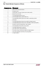
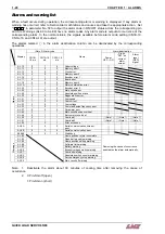
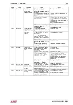
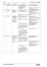
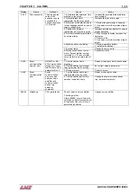
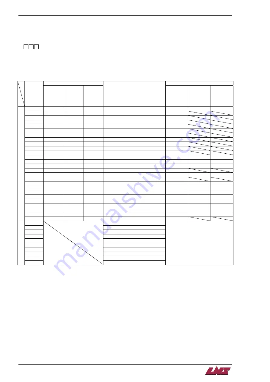
Alarms and warning list
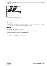
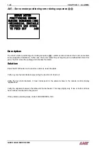
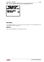
When a fault occurs during operation, the corresponding alarm or warning is displayed. If any alarm or
warning has occurred, refer to Section Alarm definitions and causes and take the appropriate action. Set
"1
" in parameter No. 59 to output the alarm code in ON/OFF status across the corresponding pin
and SG. Warnings (AL.90 to AL.E9) have no alarm codes. Any alarm code is output at occurrence of the
corresponding alarm. In the normal status, the signals available before alarm code setting (CN1B-19,
CN1A-18, and CN1A-19) are output.
The alarms marked
in the alarm deactivation column can be deactivated by the corresponding
operations.
(Note 2) Alarm code
Alarm deactivation
Display
CN1B-
19 pin
CN1A-18
pin
CN1A-19
pin
Name
Power
OFF
→
ON
Press
"SET" on
current
alarm
screen.
Alarm
reset
(RES)
signal
AL.10 0
1
0
Undervoltage
AL.12
0
0
0
Memory error 1
AL.13 0
0
0
Clock
error
AL.15
0
0
0
Memory error 2
AL.16
1
1
0
Encoder error 1
AL.17 0
0
0
Board
error
AL.19
0
0
0
Memory error 3
AL.1A
1
1
0
Motor combination error
AL.20
1
1
0
Encoder error 2
AL.24
1
0
0
Main circuit error
AL.25
1
1
0
Absolute position erase
AL.30 0
0
1
Regenerative
error
AL.31 1
0
1
Overspeed
AL.32 1
0
0
Overcurrent
AL.33 0
0
1
Overvoltage
AL.35
1
0
1
Command pulse frequency error
AL.37 0
0
0
Parameter
error
AL.45
0
1
1
Main circuit device overheat
AL.46
0
1
1
Servo motor overheat
AL.50 0
1
1
Overload 1
(Note 1)
(Note 1)
(Note 1)
AL.51 0
1
1
Overload 2
(Note 1)
(Note 1)
(Note 1)
AL.52 1
0
1
Error
excessive
AL.8A
0
0
0
Serial communication time-out
error
AL.8E
0
0
0
Serial communication error
Alarms
88888 0
0
0 Watchdog
AL.90
Home position return incomplete
AL.92
Open battery cable warning
AL.96
Home position setting warning
AL.98
Software limit warning
AL.9F Battery
warning
AL.E0 Excessive
regenerative
warning
AL.E1 Overload
warning
AL.E3
Absolute position counter warning
AL.E6
Servo emergency stop warning
Warnings
AL.E9
Main circuit off warning
Removing the cause of occurrence
deactivates the alarm automatically.
Note: 1. Deactivate the alarm about 30 minutes of cooling time after removing the cause of
occurrence.
2. 0: Pin-SG off (open)
1: Pin-SG on (short)
QUICK LOAD SERVO 65/80
Summary of Contents for Quick Load Servo 65
Page 1: ...Troubleshooting manual ENG 9 020 01 ANG ...
Page 43: ......
Page 61: ......
Page 67: ......
Page 96: ...CHAPTER 6 SPARE PARTS QUICK LOAD SERVO 65 80 6 27 020 005 413 QLS 65 80 Locking block ...
Page 99: ...CHAPTER 6 SPARE PARTS 6 30 020 005 703 QLS 65 80 Sub assembly drive QUICK LOAD SERVO 65 80 ...
Page 101: ...CHAPTER 6 SPARE PARTS 6 32 020 005 723 QLS 65 80 Sub assembly cogwheel QUICK LOAD SERVO 65 80 ...
Page 115: ...CHAPTER 6 SPARE PARTS 6 46 020 011 013 12 QLS 65 Assembly pusher ø12 QUICK LOAD SERVO 65 80 ...
Page 116: ...CHAPTER 6 SPARE PARTS QUICK LOAD SERVO 65 80 6 47 020 011 013 20 QLS 65 Assembly pusher ø20 ...
Page 117: ...CHAPTER 6 SPARE PARTS 6 48 020 011 023 6 QLS 80 Assembly pusher ø1 4 QUICK LOAD SERVO 65 80 ...
Page 118: ...CHAPTER 6 SPARE PARTS QUICK LOAD SERVO 65 80 6 49 020 011 023 12 QLS 80 Assembly pusher ø12 ...
Page 119: ...CHAPTER 6 SPARE PARTS 6 50 020 011 023 20 QLS 80 Assembly pusher ø20 QUICK LOAD SERVO 65 80 ...


