16 GB/IE
Installation
Make sure you will not be drilling into electrical,
gas or water lines inside the wall. Use a power
drill to drill the holes into the brick wall. Always
observe all safety instructions for the power drill
in the ma nual for the power drill. Death or injury
due to electric shock may otherwise result.
When selecting the mounting location, pay atten-
tion to the following:
Make sure that the spotlight
8
illuminates the
desired area. You can move the spotlight
8
vertically.
Make sure the motion detector
10
covers the
desired area. The motion detector
10
has a
maximum coverage range of max. 10 m, with
a coverage angle of about 180° (depending
on the mounting height – a height of
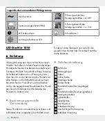
1.80–2.50 m is ideal) (Fig. D, E, F).
Make sure the motion detector
10
is not illu-
minated at night by street lighting. This can
influence its functioning.
Use the mounting bracket
2
as a pattern to
mark the drilling holes onto the wall. Ensure
that there are no cables or wires in this area
in the wall. Drill two holes (Ø 8 mm) and in-
sert the wall plugs
3
. Screw the mounting
bracket
2
with the help of the screws
1
and check the tight fit.
Open the connection box
13
by using a
crosshead screw driver to loosen the fixing
screws
17
of the connection box
13
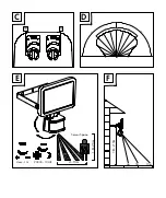
(Fig. B).
The cable gland has to be loosened, then run
the flexible supply line, e. g. type H05RN-F
3G 1.0 mm
2
, through the cable gland
16
and into the connection box
13
. Open the
terminal block
12
by using a slot head screw
driver to loosen the screws.
Attach ferrules to the wires of the supply line.
Also attach the cord anchorage
14
to the
supply line and use pliers to tighten it on the
supply line (Fig. B). Connect them with the
terminal block
12
in the connection box
13
.
Pay attention to the markings on the terminal
block
12
(L for live, N for neutral and for
the earth wire) (Fig. B). Close the terminal
block
12
again by fastening the screws.
Close the connection box
13
again by fasten-
ing the fixing screws
17
.
Now attach the spotlight
8
to the mounting
bracket
2
using the included locking screws
7
, spring washers
6
, flat washers
5
and
tooth lock washers
4
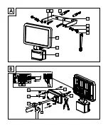
(Fig. A).
Re-install the fuse for this circuit or switch on
at the circuit breaker (I position) in the fuse
box.
Start-up
Adjusting the motion detector
Depending on the pre-adjustments of the motion
detector
10
, the product will switch itself on for a
certain period of time as soon as the motion de-
tector
10
detects movement. These pre-adjust-
ments are made using the two controllers on the
underside of the motion detector
10
(Fig. C).


