


2
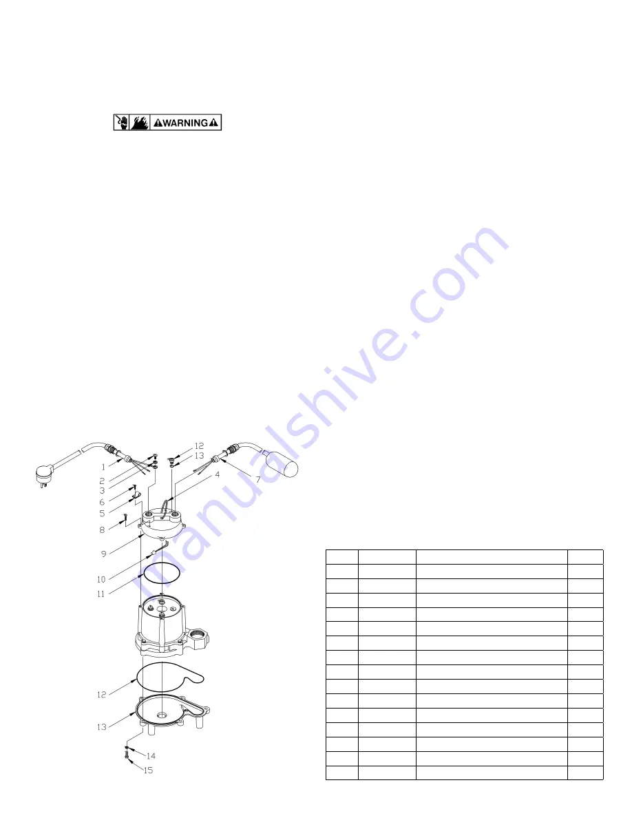
ITEM
PART NO.
DESCRIPTION
QTY.
1
951600
Wiring Harness, 15’
1
2
902437
Screw, #8-32 x 1/4
1
3
921059
Washer, Lock, #8
1
4
114100
Handle, Wire
1
5
927027
Clamp, Loop
1
6
901424
Screw, #8-32 x 1/2
1
7
950225
Switch Assembly
1
8
909022
Screw/Washer, #10-24 x 5/8
4
9
106669
Cover, Automatic
1
10
950400
Wire Nut, 14-18 AWG
1
11
928008
Seal Ring, 4.718 x .078
1
12
928040
Seal Ring, 7.928 x .063
1
13
106378
Screen/Base
1
14
921103
Washer, Lock, 1/4
6
15
903725
Screw, Cap, 1/4-20 x 7/8
6
REPLACEMENT PARTS
7. The flexible PVC jacketed cord assembly mounted to the
pump must not be modified in any way, with the exception
of shortening the cord to fit into a control panel. Any splice
between the pump and the control panel must be made within a
junction box and mounted outside of the basin and comply with
the National Electrical Code.
OPERATION
1. Pump should be installed in a suitable basin which is at least 18”
in diameter and 24” deep, in accordance with local plumbing
codes.
2. When a pump is in a basin, etc. do not touch motor, pipes or
water until unit is unplugged. If your installation has water or
moisture present, do not touch wet area until all power has been
turned off.
3. Pump features a 1-1/2“ female NPT discharge.
4. Pump must be placed on a hard level surface. Never place
pump directly on clay, earth or gravel surfaces.
5. A check valve must be used in the discharge line to prevent
back flow of liquid into the basin. The check valve should be a
free flow valve that will easily pass solids.
CAUTION: For best performance of check valves, when handling
solids install in a horizontal position or at an angle of no more
than 45 degrees. Do not install check valve in a vertical position
as solids may settle in valve and prevent opening on start-up.
6. Do not attempt to restrict the intake side of these pumps.
Restricting the intake may cause damage to the seal and may
starve the pump. If you require reduced flow rates, then place a
valve on the discharge side of the pump or if flexible vinyl tubing
is used, a clamp can be used on the tubing to restrict the flow.
7. Do not let the unit operate dry. It is designed to be cooled by
pumping fluid. You may damage the seal and the motor may fail
if the pump is allowed to run dry.
8. If the unit is going to be idle for a period of time, follow the
cleaning instructions outlined in the next section. Do not let
the unit freeze in the wintertime. This may cause cracking or
distortion that may destroy the unit.
TESTING PUMP OPERATION
NOTE:
BE CERTAIN PUMP IS SECURE IN BASIN AND FLOAT MOVES
UNOBSTRUCTED WITHOUT TOUCHING THE BASIN WALLS OR
PLUMBING.
1. These pumps are equipped with a float operated switch. When
these pumps are installed in a basin with a sealed cover, switch
operation cannot be observed. The sump cover usually will have
a spare hole that is plugged with a rubber plug. This plug can be
removed and switch operation can be observed.
2. Plug power cord into a grounded receptacle with voltage
consistent with pump voltage as indicated on pump nameplate.
3. Run water into basin until pump starts.
4. Be sure gate valve in discharge line is open.
5. Allow pump to operate through several on-off cycles.
6. If pump does not operate properly, consult the Troubleshooting
table. If trouble cannot be located with these steps shown,
consult your pump dealer or take pump to a Little Giant
authorized service center.
Figure 2.


