


APPROVAL
ENG.
MKT.
Q.C.
OF
PG.
DR.
DATE
CHANGE DESCRIPTION
INSTRUCTION SHEET
PART NUMBER
SIZE:
CN. NO.
REV.
8.5 X 11 - ONE SIDE
11 X 17 - FOUR SIDES
8.5 X 11 - TWO SIDES
Information below is for Lithonia Lighitng documentation purposes only,
DO NOT
include in Instruction sheet art.
3
3
EMCSA00601
ELU 4/ELU 4N/ELU 8 EMERGENCY LIGHTING
UNIT
A
INITIAL RELEASE
MRS
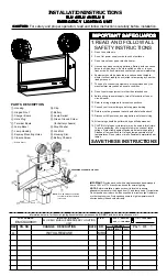
INSPECTION AND MAINTENANCE
Note: Emergency systems should be tested as often as
local codes require, or at least quarterly, to ascertain that
all components are operational.
A. NORMAL OPERATION: When unit is functioning properly,
with power applied to it, the “READY” light will be on.
B. TO TEST: Push “TEST” button. Lamps should light and
“READY” light should go out.
3. LAMP REPLACEMENT: If a lamp requires replacement,
rotate bezel
f
counterclockwise, pushing bezel slightly
toward housing
g
. When bezel tab hits the stop on
housing, pull forward and bezel will disengage. Lift out
lamp, remove wire harness leads from lamp terminals and
reconnect an identical replacement lamp. Slide bezel tabs
in housing slots and rotate clockwise until tab hits stop on
lamp housing.
4. BATTERY REPLACEMENT: Remove leads from battery
terminals (ELU4 and ELU8) or unplug the polarized battery
connector (ELU4N). Replace battery only with
manufacturer’s recommended replacement. Connect leads
as shown (Fig. 2 for ELU4N) (Fig. 3 for ELU4 and ELU8).
CAUTION: Make sure red lead is connected to positive (+)
terminal and blue lead is connected to negative (-) terminal
(ELU4 and ELU8 only).
Note: Allow battery to charge 24 hours before initial
testing, and 168 hours to fully charge battery.
Note: To ensure proper battery replacement, use part
number on battery replacement label.
5. CHARGER BOARD REPLACEMENT: Disconnect wiring
as shown (Fig. 2 for ELU4N) (Fig. 3 for ELU4 and ELU8).
Charger Board
c
is secured to battery chassis
q
by two
nylon standoffs. Depress standoff flanges and lift board
from chassis. Install replacement charger board and
reconnect wiring as shown in (Fig. 2 for ELU4N) (Fig. 3 for
ELU4 and ELU8).
Figure 3
Wiring Diagram
ELU4 and ELU8
Page 3
OR ORANGE