background image

page 4

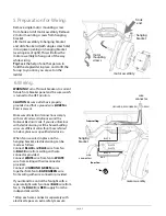
Remove single motor mounting screw 
from hook end of motor assembly. Remove 
2 motor mounting screws from hanging 
bracket.
Lift motor assembly to hanging bracket 
and slide hook end (with single screw hole) 
into square opening on hanging bracket 
(

see diagram at right

). This will allow the 

motor assembly to hang out of the way 
while wiring.

Tip

: Seek the help of another person to 

hold the stepladder in place and to lift the 
fan up to you once you are set on the 
ladder.

WARNING

: Turn off circuit breakers to current 

fixture from breaker panel and be sure switch 
is turned to the OFF position.

CAUTION

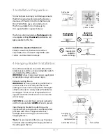
Be sure outlet box is properly 

grounded and that a ground wire (

GREEN

 or 

Bare) is present.

Make sure all electrical connections comply 
with Local Codes or Ordinances and the 
National Electrical Code. If you are unfamiliar 
with electrical wiring or if the house/building 
wires are different colors than those referred 
to below, please use a qualified electrician.

When fan is secured in place on the 
hanging bracket, electrical wiring can be 
made 


as follows:

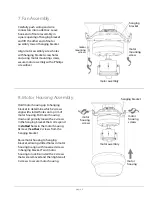
Connect 

BLACK

 and 

BLUE

 wire from fan 

to 

BLACK

 wire from ceiling with wire 

connector provided.
Connect 

WHITE

 wire from fan to 

WHITE


wire from ceiling with wire connector 
provided.
Connect all 

GROUND 

(

GREEN

) wires 

together from fan to 

BARE

/

GREEN

 wire 

from ceiling with wire connector provided.

If you intend to control the fan light with a 
separate light switch, connect 

BLUE

 wire from 

fan to the 

BLACK

 (or 

RED

) supply from the 

independent switch. 

* Wrap each wire connector separately with 
electrical tape as an extra safety measure.

5. Preparation for Wiring.

6. Wiring.

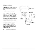
hanging
bracket

motor assembly

motor 
mounting 
screws

wire

connector

hanging
bracket

motor assembly

*

WHITE

WHITE

BLACK

BLACK

BLUE

GROUND (GREEN OR BARE)

GREEN

wire 

connectors

from ceiling

from fan

hook

end

Summary of Contents for BRC30WW6L

Page 1: ...g 2 Parts Inventory pg 2 Installation Preparation pg 3 Hanging Bracket Installation pg 3 Preparation for Wiring pg 4 Wiring pg 4 Fan Assembly pg 5 Motor Housing Assembly pg 5 Blade Assembly pg 6 Light...

Page 2: ...al injury wire connectors provided with this fan are designed to accept only one 12 gauge house wire and two lead wires from the fan If your house wire is larger than 12 gauge or there is more than on...

Page 3: ...need to be returned for repairs Check against parts inventory that all parts have been included 2 Parts Inventory a hanging bracket 1 piece b motor housing 1 piece c motor assembly 1 piece d blade arm...

Page 4: ...utlet box Arrange electrical wiring to one side of the hanging bracket Note It is very important that you use the proper hardware when installing the hanging bracket as this will support the fan page...

Page 5: ...e unfamiliar with electrical wiring or if the house building wires are different colors than those referred to below please use a qualified electrician When fan is secured in place on the hanging brac...

Page 6: ...n with slotted holes on top rim of motor housing Put motor housing down and partially loosen the 2 screws in the hanging bracket that correspond to slotted holes in the motor housing Remove the other...

Page 7: ...ning blades Remove blade arm screws and lock washers from underside of motor If plastic motor locks are installed with blade arm screws discard plastic motor locks save blade arm screws and lock washe...

Page 8: ...of the reverse switch Start at the OFF position no blade movement First pull will set the fan to HI Second pull will set the fan to MEDIUM Third pull will set the fan to LOW Fourth pull will re set th...

Page 9: ...DUSTRIES LTD will repair or replace at no charge to the original purchaser any fan motor that fails to operate satisfactorily when failure results from normal use RETURN FAN MOTOR ONLY shipping prepai...

Reviews: