background image

page >>

 33

LBL000097A

   LightForce FX User Manual, DCN: O

FX

17

>> 

  Appendix/Labels

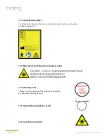
17.1 Warning Label

This label indicates the laser classification.  It warns of the radiation exposure hazard 
potential to eyes and skin.

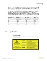
Table 16.4 - Recommended Separation Distances between portable and mobile RF 
Communications equipment and the LightForce FX (ME Equipment and ME Systems 
that are NOT Life-supporting)

The LightForce® FX is intended for use in the electromagnetic environment in which radiated 
disturbances are controlled. The customer or user of the LightForce FX can help prevent 
electromagnetic interference by maintaining a minimum distance between portable and mobile 
RF communications equipment and the LightForce FX as recommended below, according to the 
maximum output power of the communications equipment.

Max Output Power
(watts)

Separation (m)
150 kHz to 80 MHz

D=(3.5/V1)(Sqrt P)

Separation (m)
80 to 800 MHz

D=(3.5/E1)(Sqrt P)

Separation (m)
800 MHz to 2.5 GHz

D=(7/E1)(Sqrt P)

0.01

0.11667

0.11667

0.23333

0.1

0.36894

0.36894

0.73785

1

1.1667

1.1667

2.3333

10

3.6894

3.6894

7.3785

100

11.667

11.667

23.333

Summary of Contents for LightForce FX

Page 1: ...lvd Suite B Newark DE 19702 Phone 302 709 0408 Toll Free 877 627 3858 Fax 302 709 0409 FX LightForce FX with Empower Delivery System Influence Technology Perfect Protocol Deep Tissue Laser Therapy System LBL000097A LightForce FX User Manual DCN O ...

Page 2: ......

Page 3: ...raindications 6 3 5 Warnings and Cautions 6 3 6 Fire and Explosion Hazards 8 4 Glossary and Abbreviations PAGE 9 5 Features PAGE 10 6 System Set Up PAGE 12 6 1 Receipt and Unpacking 12 6 2 Usage Prerequisites 12 6 3 Set Up Location 12 6 4 Optical Fiber Connections 13 7 Empower Delivery System PAGE 15 7 1 Preparation of Patient for Laser Therapy Treatment 15 7 2 Empower Delivery System Descriptions...

Page 4: ...Information PAGE 29 and Assistance on Laser Safety 15 Warranty Information PAGE 30 15 1 Terms and Conditions 30 15 2 Return Procedure 30 16 Electromagnetic Compatibility EMC Tables PAGE 31 17 Appendix Labels PAGE 33 17 1 Warning Label 33 17 2 Identification Label 34 17 3 Non Interlocked Protective Housing Label 34 17 4 Warranty Seal 34 17 5 Optical Fiber Applicator Label 34 17 6 Laser Emission Lab...

Page 5: ...e this device unless directly supervised by a properly trained and experienced individual 1 3 Recommendation Offers guidance that may be worthy of acceptance or trial within a specific area of LightForce FX application and may serve to optimize overall utilization RECOMMENDATION Designate at least one person at each facility that utilizes this device as laser safety supervisor responsible for prov...

Page 6: ...er emission 2 Power Switch This switch is located on the bottom front of the screen on the LightForce FX Depress the switch for several seconds to turn on 3 Remote Interlock The remote interlock is located on the back of the device If the interlock is not inserted into the connector jack all electrical power to the controls and laser components is terminated The remote interlock MUST be inserted f...

Page 7: ...llows Class I Type B device according to EN IEC 60601 1 Class IIa according to Council Directive 93 42 EEC Class III according to CMDR SOR 98 282 Class 4 laser product according to IEC 60825 1 Degree of protection according to EN IEC 60601 1 IPX 0 enclosure not waterproof Ordinary protection against ingress of water Continuous operation 3 2 Regulatory Compliance 1 The LightForce FX laser complies ...

Page 8: ...es 3 5 Warnings and Cautions Warning NEVER look directly into the distal end of the optical fiber connected to an active laser device NEVER aim the laser light directly into the eyes and NEVER direct the laser beam at anything other than the area to be treated WITH or WITHOUT the appropriate laser emission protective eyewear Indirect or direct eye contact with the output beam or scattered laser li...

Page 9: ...n The protective laser eyewear supplied with this device has an optical density rating 5 0 for 810 nm and 980 nm see specification sheet laser emission All personnel present during device operation must wear this eyewear Contact LiteCure at 302 709 0408 or 877 627 3858 for US and Canada to purchase additional sets of protective eyewear for this device Caution Select a secure properly equipped and ...

Page 10: ...el to operate this device unless directly supervised by a properly trained and experienced individual Caution ALWAYS clean the SMA fiber tip before inserting into the SMA emission port A dirty tip could result in damage to the device 3 6 Fire and Explosion Hazards Health care professionals should be aware of the following safety considerations and potential fire hazards when using the laser 1 The ...

Page 11: ...Frequency Laser pulse repetition rate Hertz Measuring unit for frequency pulses per second Remote Interlock Safety device that stops laser radiation when the Remote Interlock Circuit is opened Joule Unit of measure for emitted energy Watt Unit of measure for laser power Stop End of treatment or treatment break 4 Glossary and Abbreviations Abbreviation Definition cm2 Square Centimeter Hz Hertz s Se...

Page 12: ...A LightForce FX User Manual DCN O FX Touch Screen Interface 5 Features Front View Emergency Laser Stop Display LED Indicator Warranty Seal Label Finger Switch Optical Port Bottom View Power Switch Fiber Managment System ...

Page 13: ...page 11 LBL000097A LightForce FX User Manual DCN O FX Back View Foot Switch Receptacle Remote Interlock Receptacle DC Power Cord Receptacle USB Port ...

Page 14: ...r orientation and education sessions to achieve operational proficiency Every facility or institution utilizing this device is encouraged to adopt an ongoing training and safety program 6 3 Set Up Location 1 Select a secure properly equipped and well ventilated location in which to install and operate the laser device 2 Ensure that the surface will properly support the entire device 3 Place the de...

Page 15: ...aging 3 Remove protective cap from the end of the fiber optic cable 4 Carefully insert end of fiber optic cable into optical port 5 Thread connector onto optical port until tight Caution If the optical port or the fiber tip is contaminated then the device can be damaged during beam emission Do not remove the hand piece fiber from the emission port once it has been secured unless the device is bein...

Page 16: ...amaged during beam emission The dust cap is installed by the manufacturer as a means to prevent dust and debris from contaminating the emission port during shipping and before device installation and is not intended as the primary means to protect the emission port connector during normal use We Recommend The Following Procedure 1 Before using the device for the first time install and secure the o...

Page 17: ...pletely evaporates Doing so may cause the laser to ignite alcohol solutions or vapors Hand Piece and Finger Switch 7 2 Empower Delivery System Descriptions 1 The Empower DS is composed of a double sheathed optic fiber and a hand piece with interchangeable treatment heads Warning This laser device is not intended for operation in areas subject to explosion hazards such as flammable materials gases ...

Page 18: ... skin 140mm with 10cm from the patient skin 4 7m Large Ball Large Cone Small Ball Small Cone Small Cone Small Ball Large Ball Large Cone 2 Exchange treatment head securely tighten the new hand piece head to hand piece handle Laser Hand Piece Style NOHD meters Beam Divergence Small Cone 1 8 m Full Angle degrees 47 Large Cone 1 8 m Full Angle degrees 47 Small Ball 6 2 m Full Angle degrees 12 Large B...

Page 19: ...n during treatment is desired This head should be perpendicular to the skin and not approaching at an angle The area to be treated and a significant surrounding margin should be covered evenly in a painting or serpentine motion The Large Cone Head can be used at power settings up to 15 W 8 cm from the skin of the patient Hand Piece with Finger Switch and Large Ball This treatment head is for use i...

Page 20: ...ecommend the following procedure 1 Before using the device for the first time install and secure the hand piece fiber into the laser emission port in accordance with section 6 4 2 Use the device as required 3 When done using the device power off and leave the hand piece connected 4 If the tip is contaminated clean it with the fiber cleaning paper provided with the device Bending Limits of the Hand...

Page 21: ... laser safety sign or its equivalent on the outside of the treatment room door when the laser is in use 2 Close the treatment room door during operation of the laser Or optionally the Interlock Jack can be connected to the treatment room door through an interlock circuit so that laser emission is automatically disabled when the treatment room door is opened A blocking barrier screen or curtain cap...

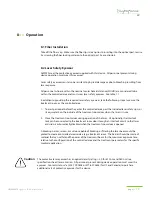
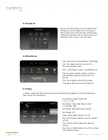
Page 22: ... mW Unit Volume Tone High Med and Low a 45 65 dB at High Unit Volume Beep High Med and Low Unit Volume Off Finger Foot Switch Override On Off Press Save Changes button to save the selected settings Press Cancel button to cancel the selected settings Press Reset to Default button to reset the settings to the default settings 8 4 Main Menu Press Protocols to initiate Influence Technology Press the O...

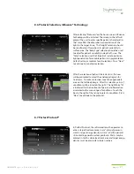
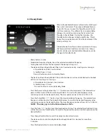
Page 23: ...or all selections Press Next to continue to condition selection After the selection of patient characteristics the user will be prompted to select the anatomical region for treatment To make a selection touch the appropriate area on the full body image After this selection a list of conditions will be listed on the right The LightForce FX is indicated for the treatment of pain and inflammation ass...

Page 24: ...mes Press exit button to return to Standby Mode Rotate the power knob or press or the button to set the laser power The selected laser power will be shown at the Power Setting Window To scroll to the desired power value maintain pressure on the desired button The laser power can be set from 0 5 W to 15 W Press the Pulsed Rate button to set the laser modulation frequency The selected laser frequenc...

Page 25: ...rn to Standby Mode The device will leave Ready Mode if the remote interlock is not inserted attached to the back of the unit creating error message a Operation Error Interlock is not inserted b Audible beep 3 times Press exit button to return to Standby Mode Press the Power Setting Scale or the button to set the laser power The selected laser power will be shown at the Power Setting Window To scro...

Page 26: ...ble beep 3 times c Laser beam is disabled Press exit button to return to Standby Mode The device will exit from Emission Mode if the remote interlock is not inserted creating error message a Operation Error Interlock is open b Audible beep 3 times c Laser beam is disabled Press exit button to return to Standby Mode The device will exit from Emission Mode if the laser power is out of range creating...

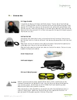
Page 27: ...ch stops laser emission When closed the cover of the foot switch is designed to prevent inadvertent foot pedal control surface depression Always turn the laser off when not in use When foot switch operation is desired press down on the cover then release The cover is spring loaded and will open automatically 9 3 AC Power Cord 9 4 Power Adapter 9 5 Laser Safety Eyewear 9 Accessories Caution ALWAYS ...

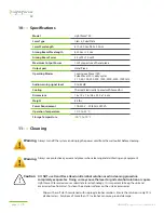
Page 28: ... x 25 5 x 18 cm 8 5 lbs 100 240 V 50 60 Hz 250 VA 10 o C to 32 o C 20 o C to 70 o C Caution DO NOT use Hand Piece Head until alcohol solution used in cleaning procedure completely evaporates Doing so may cause the laser to ignite alcohol solution or vapors LightForce FX laser device uses solid state laser technology It is important to keep the unit and accessories free from dust To clean the exter...

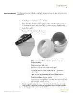
Page 29: ...efore cleaning turn off the system and unplug the power cord from the wall outlet Avoid using soiled or gritty cloths Remove the elastic band from the hand piece head Unscrew the top portion of the Large Ball take care to retain the spacer ring The ball can now be removed from the housing unit for cleaning Always dampen the cloth before cleaning After cleaning ensure that all cleansers have been r...

Page 30: ... finger switch and power cord as directed in the manual Pay special attention to ensuring that both ends of the optical fiber are clean and free of any dust fluid or other contaminants 3 Turn on the LightForce FX and enter Standby Mode as instructed in the manual 4 Increase the power setting until the Digital and Analog Power Displays reach their maximum setting in CW Continuous Wave 5 Place the l...

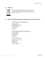
Page 31: ... Institute of Medical Laser Applications 18070 Raymond Road Marysville Ohio 43040 Phone 937 209 0271 Fax 937 642 7880 www aimla org Laser Institute of America 12424 Research Parkway Suite 125 Orlando FL 32826 Phone 407 380 1553 Fax 407 380 5588 www laserinstitute org If you plan to discontinue the use of this laser and intend to dispose of it make sure to observe the applicable legal provisions Pl...

Page 32: ...d by purchaser LiteCure will return repaired or replaced products to purchaser with FOB city destination within the Continental United States Transportation fees insurance if necessary beyond this limit will be charged to the purchaser 15 2 Return Procedure Please review terms of purchase and date of shipment to determine validity of warranty claim Warranty claim should only be made for products w...

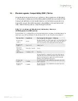
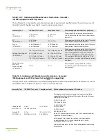
Page 33: ...ld ensure that it is used in such an environment Emissions Test Compliance Electromagnetic Environment Guidance RF Emissions CISPR 11 Group 1 The LightForce FX uses RF energy only for its internal function Therefore its RF emissions are very low and are not likely to cause any interference in nearby electronic equipment RF Emissions CISPR 11 Class A or B Failed Class A Harmonics IEC 61000 3 2 Clas...

Page 34: ...FX requires continued operation during power mains interruptions it is recommended that the LightForce FX be powered from an uninterruptible power supply or battery Power Frequency 50 60 Hz Magnetic Field IEC 61000 4 8 3 A m 3 A m Power frequency magnetic fields should be that of a typical commercial or hospital environment Table 16 3 Guidance and Manufacturer s Declaration Immunity ME Equipment a...

Page 35: ...netic environment in which radiated disturbances are controlled The customer or user of the LightForce FX can help prevent electromagnetic interference by maintaining a minimum distance between portable and mobile RF communications equipment and the LightForce FX as recommended below according to the maximum output power of the communications equipment Max Output Power watts Separation m 150 kHz t...

Page 36: ... model number serial number and regulatory compliance declarations 17 3 Non Interlocked Protective Housing Label 17 4 Warranty Seal Labels are on the underside of the laser device to indicate any attempt to open the housing 17 5 Optical Fiber Applicator Label 17 6 Laser Emission Label WARRANTY VOID IF SEAL IS BROKEN ...

Page 37: ...anual DCN O FX 17 7 Emergency Laser Stop Label 17 8 Finger Foot Switch Label 17 9 Remote Interlock Connector Label 17 10 CE Mark Label 17 11 DC Power Input Label 17 12 Protective Earth Ground Label Inside Device 17 13 Power Switch Label STOP ...

Page 38: ...ial number ready as Customer Care will need this information to provide you with the highest level of service Please also be prepared to provide your unit model s name Contact LiteCure Medical 250 Corporate Blvd Suite B Newark DE 19702 Phone 302 709 0408 Toll Free 877 627 3858 Fax 302 709 0409 LightForceLasers com info LightForceLasers com ...

Page 39: ......

Page 40: ...Back in Action Faster LiteCure Medical 250 Corporate Blvd Suite B Newark DE 19702 Phone 302 709 0408 Toll Free 877 627 3858 Fax 302 709 0409 FX LightForceLasers com LBL000097A LightForce FX User Manual DCN O ...

Reviews: