background image


CX-2401


24ch. ModularDimmer Console


Lite-Puter

13

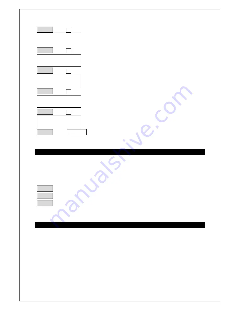
STEP-3:

press 

÷

STEP-4:

press 

ù

STEP-5:

press 

÷

 two times

STEP-6:

press 

ù

STEP-7:

press 

÷

 two times to finish setting.

STEP-8:

press   

ENTER 

 to confirm.

3-8-2. Executing “ X-FADE”

The same example as above

To display scene 2, scene 4 and scene 6 dimming output by pressing 

X-FADE VR.

STEP-1

:push 

"X-FADE VR" 

up to the top to output scene 2. (step 1)

STEP-2

:pull

 "X-FADE VR" 

down to the bottom to output scene 4. (step 2)

STEP-3

:push 

"X-FADE VR" 

up to the top to output scene 6. (step 3)

3-8-3. Stop “ X-FADE”   

Pull 

"X-FADE VR" 

down to the bottom and then press 

HOT KEY

 to stop x-fade

output.

1.XFADE EDIT
STEP   1 =SC   2

1.XFADE EDIT
STEP   2 =SC   2

1.XFADE EDIT
STEP   2 =SC   4

1.XFADE EDIT
STEP   3 =SC   4

1.XFADE EDIT
STEP   3 =SC   6

Summary of Contents for CX-2401

Page 1: ...CX 2401 24CH Modular Dimmer Console User Manual Lite Puter Enterprise Co Ltd Website http www liteputer com tw E mail litecom ms2 hinet net EXTENSIBLE MODULE DESIGN...

Page 2: ...e module front panel discription 5 2 3 Master module Slave module rear panel discription 6 Chapter 3 Operation 3 1 A1 A2 7 3 2 How to set and execute the scene under A1 mode 8 3 3 How to set and execu...

Page 3: ...ule design CX 2401 dimmer console is designed to be a simple and easy operation machine Because it is absolutely operated by one channel to one channel mode a big control panel is necessary Therefore...

Page 4: ...ut 12 scenes by VR or HOT KEY and total 120 scenes at most l 2 independent cross faders A and B l X FADE Each program file can be programmed up to 120 steps each step corresponds to a certain scene l...

Page 5: ...L SLAVE 24 Chapter 2 CX 2401 module installation 2 1 Standard and extend type Merit flexible channel number easy maintenance and update software Standard set to control 24 ch Extended set 7 dimmer mod...

Page 6: ...ster VR for A scene VR A 11 Master VR for B scene VR B 12 VR for dimming level under AUDIO function 13 VR for speed of channel output 14 X FADER clearance key 15 VR for dimming level under CHASE funct...

Page 7: ...tion MASTER rear panel SLAVE rear panel 1 Power Switch 2 DMX 512 output 3 DMX 512 output 4 AC power socket 100 240 V AC 5 Midi signal output 6 Midi signal input 7 Rs232 D type socket 9 Pin 8 Audio soc...

Page 8: ...modes to change the scene immediately and meet the user s need A1 Top line the channel dimming level of A scene Bottom line preset dimming level for B scene A2 Top line to set and call out the scene B...

Page 9: ...1 push master module MASTER VR to the top STEP 2 press F1 to chooce MODE A1 STEP 3 press ENTER to confirm 3 2 2 To set dimming level for A B scenes STEP 1 Push slave module VR on top line to ideal dim...

Page 10: ...tion key 120 scenes can be set at most STEP 1 push master module VR A VR B to the top STEP 2 push slave module SC 1 SC 24 top line and CH 1 CH 24 bottom line to ideal dimming level STEP 3 press F4 to...

Page 11: ...ttom line will display the channels of scene1 Method 2 call out by HOT KEY 1 24 switch output Press HOT KEY 1 24 top line to call out scene 1 switch output and leave the key to stop output 3 4 How to...

Page 12: ...eed channel 1 channel 24 Under A2 mode scenes chasing STEP 1 to confirm A2 mode refer 3 3 1 STEP 2 push master module CHASE VR to the ideal lighting level STEP 3 push master module SPEED VR to the ide...

Page 13: ...e module SC 1 SC 24 for your need scene 1 scene 24 3 6 3 Chasing controlled by MIDI Output is controlled only by MIDI 3 7 How to stop chasing Pull CHASE VR down to the bottom 3 8 Scenes X FADE 3 8 1 S...

Page 14: ...and scene 6 dimming output by pressing X FADE VR STEP 1 push X FADE VR up to the top to output scene 2 step 1 STEP 2 pull X FADE VR down to the bottom to output scene 4 step 2 STEP 3 push X FADE VR up...

Page 15: ...ult of that the MIDI CHANNEL level in CX 2401 has to be corresponding to the CHANNEL level of MIDI interface then CX 2401 can receive the data correctly from MIDI interface TONE can send 128 different...

Page 16: ...LCD background lighting level STEP 1 press F3 and press four times STEP 2 press ENTER and then press or to adjust background lighting level 3 9 5 Inspection Step 1 press F3 and press five times p s th...

Reviews: