36
GAMMA SERIES ENGINES OpERATORS' hANdbOOk
28
GAMMA SERIES ENGINES OPERATORS' HANDBOOK
1.Place a tray under the filter to collect
spilt lubricating oil.
2.Remove the filter canister with a strap
wrench or similar tool. Ensure that
the adaptor
(Figure 5.10)
is secure
in the filter head, and then discard
the canister.
3.Clean the filter head .
4.Add clean lubricating oil to the new
canister. Allow the oil enough time to
pass through the filter element.
5.Lubricate the top of the canister seal
with clean lubricating oil.
6 .Fit the new canister and tighten it
by hand only. Do
NOT
use a strap
wrench.
7. Ensure that there is lubricating oil in
the sump. On turbocharged engines,
ensure that the engine will not start
and operate the starter motor until oil
pressure is obtained. To ensure that
the engine will not start, either put
the manual stop control in the
stop
position or disconnect the electrical
stop control of the fuel injection
pump. Oil pressure is indicated when
the warning light is extinguished or
by reading a gauge.
8.Operate the engine and check for
leakage from the filter. When the
engine has cooled, check the oil level
on the dipstick and put more oil into
the sump if necessary.
5.11 CLEANING THE
BREATHER SYSTEM
Refer to
Figure 5.11
.
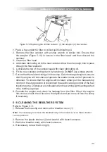
1.Release the hose clip and remove
the breather cover (1).
Note:
It is necessary to remove the breather
body in the rocker cover so that a strainer
can be put into it.
2.Remove the plastic strainer (2) and
wash it with clean kerosene.
3.Wash the breather body with clean
kerosene.
4.lf necessary, renew the O-ring (3).
Figure 5.11 Cleaning the breather system. (1)
breather cover; (2) plastic strainer; (3) O-ring.
5.Check that the inside of the upper
pipe is clean. If the pipe is not clean,
release the flange setscrews and
remove the pipe. Wash the pipe with
kerosene and dry with low pressure air.
6.Fit the breather cover onto the body
and ensure that it is fitted firmly.
7.Fit the upper pipe and tighten the
hose clip.
Note:
The breather body is fixed on the
cover with screws. If it is necessary to
remove the breather assembly, use a
spanner to clamp the flange on the bottom
before loosening the screws.
5.12 SERVICING THE AIR
CLEANER
A typical wet -type air cleaner is shown
in
Figure 5.12
. The wet type air cleaner
must be drained regularly.
1.The container and element (1) must
be cleaned with kerosene or with
another suitable fluid . Do
NOT
use
gasoline.
2.Check that the seal (2) is not
damaged. Renew it if necessary.
3.Fill to the indicated level (3) with
clean engine lubricating oil.
Figure 5.11 Cleaning the breather system. (1) breather cover; (2) plastic strainer; (3) O-ring
5. Check that the inside of the upper pipe is clean. If the pipe is not clean, release
the flange setscrews and remove the pipe. Wash the pipe with kerosene and
dry with low pressure air.
6. Fit the breather cover onto the body and ensure that it is fitted firmly.
7. Fit the upper pipe and tighten the hose clip.
Note:
The breather body is fixed on the cover with screws. If it is necessary to remove the
breather assembly, use a spanner to clamp the flange on the bottom before loosening the
screws.
5.12 SERvICING ThE AIR ClEANER
A typical wet type air cleaner is shown in
Figure 5.12.
The wet type air cleaner
must be drained regularly.
1. The container and element (1) must be cleaned with kerosene or with another
suitable fluid. Do
NOT
use gasoline.
2. Check that the seal (2) is not damaged. Renew it if necessary.
3. Fill to the indicated level (3) with clean engine lubricating oil.
29
GAMMA SERIES ENGINES OPERATORS' HANDBOOK
Figure 5.12 A typical wet type air cleaner.
5.12.1 Air Filter
Environmental conditions have an
important effect on the frequency at
which the air filter needs service
Refer to
Figure 5.12.1
.
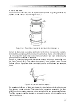
Figure 5.12.1 The air filter, showing the
dust bowl (1) and element (2).
Certain air filters have a separate dust
bowl (1) which must be cleaned at
intervals. Do not let dust completely
fill the bowl as this will reduce the life
of the filter element (2). The amount
of dust in the bowl indicates whether
it has been removed early enough for
the conditions of operation.
Certain air filters have automatic dust
valves through which dust is expelled
from the filter
(Figure 5.12.2)
. The
rubber dust valve (1) must be kept
clean. Ensure that the sides of the
valves close completely together and
that they can separate freely.
Figure 5.12.2 Air filter with dust valve (1).
If a restriction indicator is fitted (see
below) it will indicate precisely when the
air filter element needs servicing. This
prevents the premature removal of the
filter, which is an unnecessary expense,
or late removal which can cause loss
of power. The filter element must be
cleaned or renewed according to the
manufacturer's recommendations.
5.12.2 Restriction Indicator
The restriction indicator for these
engines must work at a pressure
difference of 508/558mm (20/22 in) of
water gauge.
It is fitted on the outlet pipe of the air
cleaner.
Refer to
Figure 5.12.3
. When the red
warning light (1) is seen through the
clear panel (2) after the engine has
stopped, the air filter element must be
Figure 5.12 A typical wet type air cleaner.
Summary of Contents for GW3
Page 59: ...59 ...


