8
AudioConnect
TM
Manual
Configure Listen Hardware
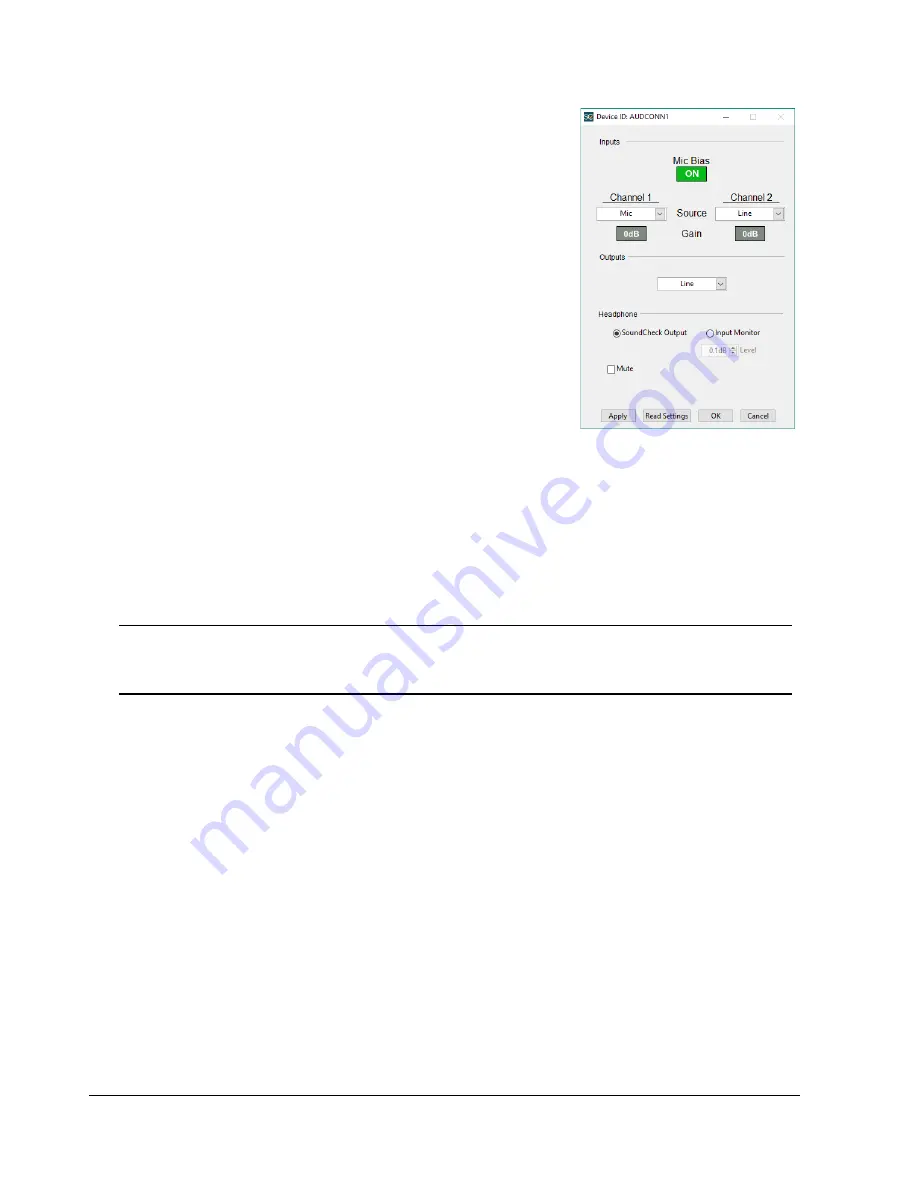
The Message Step for AudioConnect in
shows the default
settings for AudioConnect.
Mic Bias
Turns the 9.5 VDC microphone bias On and Off for both
microphone input channels
Gain
Select 0 dB or +20 dB independently for channels 1 & 2
Input select
Select Mic or Line Input independently for channels 1 & 2
SoundCheck Hardware Editor Vp values automatically adjust
when AudioConnect input channels are switched between mic
and line via Message steps in a sequence
Output select
The output should be set to Line
Digital Out is currently not available.
Headphone
SoundCheck Output
- Allows you to monitor the Output of the audio interface at the Headphone
jack. Use this setting if using the output for Headphone testing.
For use in headphone testing, the gain is fixed at 0.1 dB. The headphone out should be
calibrated in the SoundCheck Calibration Editor. The Headphone Amp Calibration Sequence
should be used. See
Headphone Amp Calibration on page 5
Note:
Prior to serial number 40501270109, firmware 1.61, the headphone output polarity is inverted
for both channels. Polarity tests using the headphone out will need to be adjusted accordingly.
Polarity Limits may need to be changed from a Lower Limit of 0 to an Upper Limit of 0.
Input Monitor
- Used to listen to the Input of the audio interface. Use this setting when verifying the
signal coming into SoundCheck.
Monitor level default is approx -16 dB
Apply
- Click to send the current setting to the device
Read Settings
- Click to get the current settings of the connected device
OK/Cancel
- Click to close the device editor or message step
OK accepts the changes
Cancel will ignore the changes and return to the previously saved state
For more information on the use of Message Steps in a SoundCheck, please refer to the Message Editor
chapter of the SoundCheck Manual.
Analysis
AudioConnect requires that all Analysis Steps in SoundCheck sequences use Auto Delay on the Delay Tab.
Figure 4-3: Device Settings
Summary of Contents for AudioConnect Series
Page 2: ...Rev 030519...
Page 4: ...ii Contents AudioConnectTM Manual Page Intentionally Left Blank...
Page 6: ...iv AudioConnectTM Manual Limited Warranty Page Intentionally Left Blank...
Page 8: ...2 AudioConnectTM Manual Introduction Page Intentionally Left Blank...
Page 19: ...Block Diagram AudioConnectTM Manual 13 Block Diagram...
Page 20: ...14 AudioConnectTM Manual Block Diagram Page Intentionally Left Blank...
Page 26: ...20 Declaration of Conformity AudioConnectTM Manual Declaration of Conformity...


