Lissmac CDM 46 W Operating Manual Download Page 7

7/30 


DESCRIPTION OF PERFORMANCE 


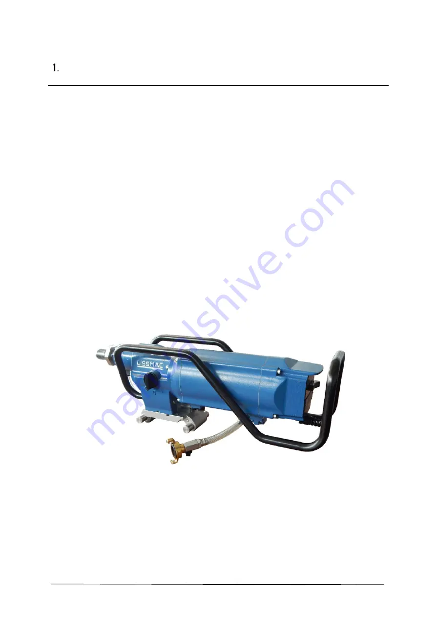
With their compact, robust design, the CDM 46 W and CDM 63 W provide reliable, user-friendly, 

professional wet drilling every day on the construction site. The closed core drill motor (water 
cooled) enables easy overhead drilling without any sealing measures. The careful design of the 
safety clip secures the core drill in the harsh construction site environment as well as acting as a 
functional handle for daily transport and simple mounting on drilling stands.  


User-friendly - Three gear levels permit optimum speed selection adapted to the specific core 
drill diameter 


Drill crown collet with integrated spindle protection 


Electro-mechanical on/off switch on the control box is quick and easy to operate even in 
difficult situations 


MULTI-TRONIC 


The integrated, automatic phase inverter spares controlling the direction of rotation of the 
drill spindle – it automatically regulates the direction of rotation 


Overload protection for the maximum possible operating comfort and long service life - 
Stotter Elektronik 


Integrated smooth start makes operation easier when starting the drilling process  


Maximum safety due to electronic and mechanical overload coupling as well as additional 
thermal overload protection 


Summary of Contents for CDM 46 W

Page 1: ...ANUAL DIAMOND CORE DRILL MOTOR CDM 46 W CDM 63 W LISSMAC Maschinenbau GmbH Lanzstrasse 4 D 88410 Bad Wurzach Telephone 49 0 7564 307 0 Fax 49 0 7564 307 500 lissmac lissmac com www lissmac com CONSTRU...

Page 2: ...2 30...

Page 3: ...ax 49 0 7564 307 500 lissmac lissmac com http www lissmac com Translation of the original operating manual Status 06 2015 The dissemination or duplication of this operating manual in any form or the r...

Page 4: ...ote Indicates that with non compliance damage to the machine or other materials or property damage can possibly occur Handling information for operators The defined sequence of the handling steps make...

Page 5: ...f work removing waste as a result of drilling work machine maintenance removal of work material Maintenance service inspection repair etc In addition to the specifications and instructions in this ope...

Page 6: ...6 30 Notes...

Page 7: ...els permit optimum speed selection adapted to the specific core drill diameter Drill crown collet with integrated spindle protection Electro mechanical on off switch on the control box is quick and ea...

Page 8: ...This core drill motor must be mounted in a drill stand in order to work properly and safely There must be uninterrupted cooling of the core drill motor with water available during drilling Intended us...

Page 9: ...r in construction zones Use of this machine in a manner not described in the operating manual is considered improper 1 3 General safety instructions ATTENTION Read through the following instructions s...

Page 10: ...zardous to your health Wear hearing protection where the noise level is 90 dB A and above 1 3 8 Dust extraction systems Equipment on which a dust extraction system must be installed must be equipped w...

Page 11: ...r switch when transporting equipment so that it is not accidentally switched on 1 3 15 Always practice caution Never use any equipment if you are under the influence of drugs or alcohol Always keep yo...

Page 12: ...tion GEKA Pos 6 QUICK LOC fixture Pos 7 Motor mounting plate Pos 8 Gear switch Pos 9 Drill crown collet 2 2 Scope of delivery 4 m power cable with 400V CEE 16A plug without mechanical phase inverter G...

Page 13: ...vel III 570 1 min 440 1 min Spindle speed with full load Gear level I 150 1 min 110 1 min Gear level II 320 1 min 250 1 min Gear level III 480 1 min 395 1 min Height 185 mm 185 mm Width 190 mm 190 mm...

Page 14: ...or unauthorised tools is prohibited Damaged tools must not be used Depending on the application purpose and area tools are different To have the best results the parameters must match For this the ma...

Page 15: ...machine Drilling without a core drill stand is not intended use and is prohibited The core drill motor is connected with the core drill stand via the QUICK LOC plate For this the mounting plate is scr...

Page 16: ...he water seals on the core drill motor The water pressure must be maximum three bar Notice whether excessive vibrations occur on the core drill If vibrations are too high the drill can possibly jam or...

Page 17: ...ng on the application purpose and area tools are different To have the best results the parameters must match With this diagram the optimal cutting performance can be determined Note In the LISSMAC sa...

Page 18: ...t is due to a material or processing error Parts that have been subject to normal wear and tear or are damaged due to improper use are not included in this warranty Exceptions to the warranty are Driv...

Page 19: ...19 30 CONDITIONAL CONNECTIONS Conditional connections according to EN 61000 3 3 2009 or IEC 61000 3 11 RA 0 15 jXA 0 1 on 50 Hz RN 0 1 jXN 0 06 on 50 Hz G G G RA iXA L1 RA iXA RA iXA RN jXN L2 L3 N...

Page 20: ...1 X 3 WATER SUPPLY RING 1 X X 4 SHAFT SEALING RING 1 X X 5 SHAFT SEALING RING 1 X X 6 SHAFT SEALING RING OD 50x7 h 1 X X 7 COMPRESSION BALL BEARING 51106 1 X X 8 NEEDLE BEARING 1 X X 9 THRUST BEARING...

Page 21: ...W 1 X 3 WATER SUPPLY RING 1 X X 4 SHAFT SEALING RING 1 X X 5 SHAFT SEALING RING 1 X X 6 SHAFT SEALING RING OD 50x7 h 1 X X 7 COMPRESSION BALL BEARING 51106 1 X X 8 NEEDLE BEARING 1 X X 9 THRUST BEARI...

Page 22: ...G 1 X X 34 CYLINDER HEAD SCREW M5x12 1 X X 35 GEAR SHIFT LEAVER 1 X X 36 GEAR SHIFT KNOB 1 X X 39 LOCKING RING M5 1 X X 114 1006302 ROTOR CDM 46 W CPL X X 55 SEALING RING 1 X X 56 SHAFT WASHER 1 X X 6...

Page 23: ...X 96 1 ROUND HEAD PHILIPS HEAD SCREW 2 X X 97 4 SEAL 1 X X 98 SWITCH COVER 1 X X 99 ROUND HEAD PHILIPS HEAD SCREW 4 X X 100 CONNECTING PIECE 1 X X 117 1006310 DRIVE CDM 63 W CPL X X 55 SEALING RING 1...

Page 24: ...le fitting 1 X X 97 4 SEALING RING 2 0x16 7x21 1 X X 121 1006315 CONNECTION WATER SCREWED CONNECTION CPL X X X 74 SPACER BLOCK 1 X X 75 O RING 1 X X 76 PAN HEAD SCREW 4 X X 122 1006316 SERVICE Kit CDM...

Page 25: ...44 1008504 BRAKE DISC 5 X 45 1008505 BRAKE DISC 2 X 46 1008506 NEEDLE BEARING 1 X 47 1008496 BRAKE DISC 46 7x 26 1x7 1 X X 51 1008501 NEEDLE BEARING HK 2016 1 X X 52 1008502 HEXAGON NUT M22xP1 5x18 mm...

Page 26: ...26 30 CDM 46 W 400 V Stand 21 01 2015 118 118 117 117 112 112 110 110 115 115 114 114 119 119 116 116 120 120 121 121 113 113 SERVICE KIT 122 122 111 111 111 111...

Page 27: ...27 30 CDM 63 W 400 V Stand 21 01 2015 114 114 117 117 112 112 110 110 115 115 116 116 118 118 119 119 120 120 121 121 113 113 SERVICE KIT 122 122 111 111 111 111...

Page 28: ...28 30 CDM 20 U CDM 20 W 230V YELLOW GREEN BLUE 2 1 3 4 GREEN YELLOW RED 19 05 2015 46 63 W 400...

Page 29: ...ine conforms to the relevant provisions of Directive 2006 42 EC Manufacturer LISSMAC Maschinenbau GmbH Lanzstrasse 4 D 88410 Bad Wurzach Technical documentation retained by LISSMAC Maschinenbau GmbH L...

Page 30: ...30 30...

Reviews: