TME-104P-CSR-LX800-R1V5.doc
Rev 1.5
26 (44)
3.16
Reset-In Signal
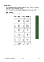
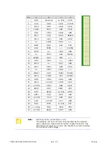
The "Reset-In" signal is located on the IDC10 Header PS/2. To reset the board, the signal "Reset-In"
must be pulled to GND.
Connector type IDC10 pin header 2.54 mm
Pin
Signal
Pin
Signal
1
Speaker
2
Mouse Clock
3 Reset-In 4
Mouse Data
5
KB Data
6
KB Clock
7 GND 8
+5 Volt Standby
9
Ext. Battery
10
Power Button
3.17
PC/104-Plus Bus Interface
The PC/104-Plus bus is a modification of the standard PCI bus. It allows all of the PC/104 features to
be used, together with the high speed PCI bus.
The main features are:
•
PC/104-Plus Bus slot, fully compatible with PCI version 2.2 specifications.
•
Integrated PCI arbitration interface (32 bit wide, 3.3V).
•
Translation of PCI cycles to ISA bus.
•
Translation of ISA master initiated cycle to PCI.
•
Support for burst read/write from PCI master.
•
33 MHz PCI clock.
Note:
The 3.3 V pins on the PC/104 Plus bus are not supplied by the
onboard 3.3 V power supply. If a PC/104 Plus peripheral board is
used that needs 3.3V from the bus as power the customer must
supply this voltage by himself.

