4
432-LIPPERT (432-547-7378)
Rev:06.30.22
JT’s Strong Arm
™
Travel Trailer
Installation and Owner’s Manual
(For Aftermarket Applications)
CCD-002345
Preparation
1.
Make sure to park the trailer on solid, level ground.
2.
Clear all jack landing locations of debris and
obstructions.
3.
Locations should be free of depressions.
4.
When parking trailer on extremely soft surfaces, utilize
load distribution pads under each jack.
5.
People and pets should be clear of trailer while
operating leveling system.
Resources Required
Installation
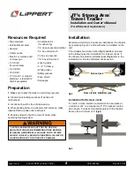
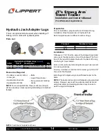
Determine which style of jacks are installed on the chassis
by comparing Figure 1 and 2 with what is installed on the
unit.
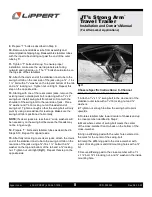
If the chassis has scissor jacks
(Fig.1)
installed, proceed
to the following section Installation for Scissor Jacks. If
the chassis has electric stabilizer jacks
(Fig.2)
refer to the
Installation for Electric Stabilizer Jacks section.
Fig.2
Rear electric stabilizer jack
Fig.1
Scissor jack
•
Tape measure
• Felt-tip black marker
•
Hammer
•
Center punch
• Electric or cordless drill
or screw gun
•
1/8
” drill bit
(for pilot holes)
•
5/16
” drill bit
•
3/8
” drill bit
•
1/2
” “Uni-bit,” or step bit,
preferred
—
standard
1/2
”
drill bit acceptable
•
Countersink bit
(for deburring)
•
9/16
” deep socket and ratchet
•
9/16
” box end wrench
•
5/8
” box end wrench
•
11/16
” box end wrench
• Locking pliers
•
3”- 4” C-Clamp
• White grease
• Safety glasses
• Face shield
•
Squeegee
THE TRAILER MUST BE SUPPORTED PER THE
MANUFACTURER’S RECOMMENDATIONS BEFORE
WORKING UNDERNEATH. FAILURE TO DO SO MAY
RESULT IN DEATH, SERIOUS PERSONAL INJURY OR
SEVERE PRODUCT OR PROPERTY DAMAGE.
Installation for Scissor Jacks
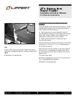
1.
Locate a cross-member rearward of the rear jacks at
a minimum of 4” to a maximum of 18” for jacks mounted
at an angle. For jacks mounted square with the chassis
frame, use a minimum of 6”
(Fig.3)
.
Fig.3
6”

