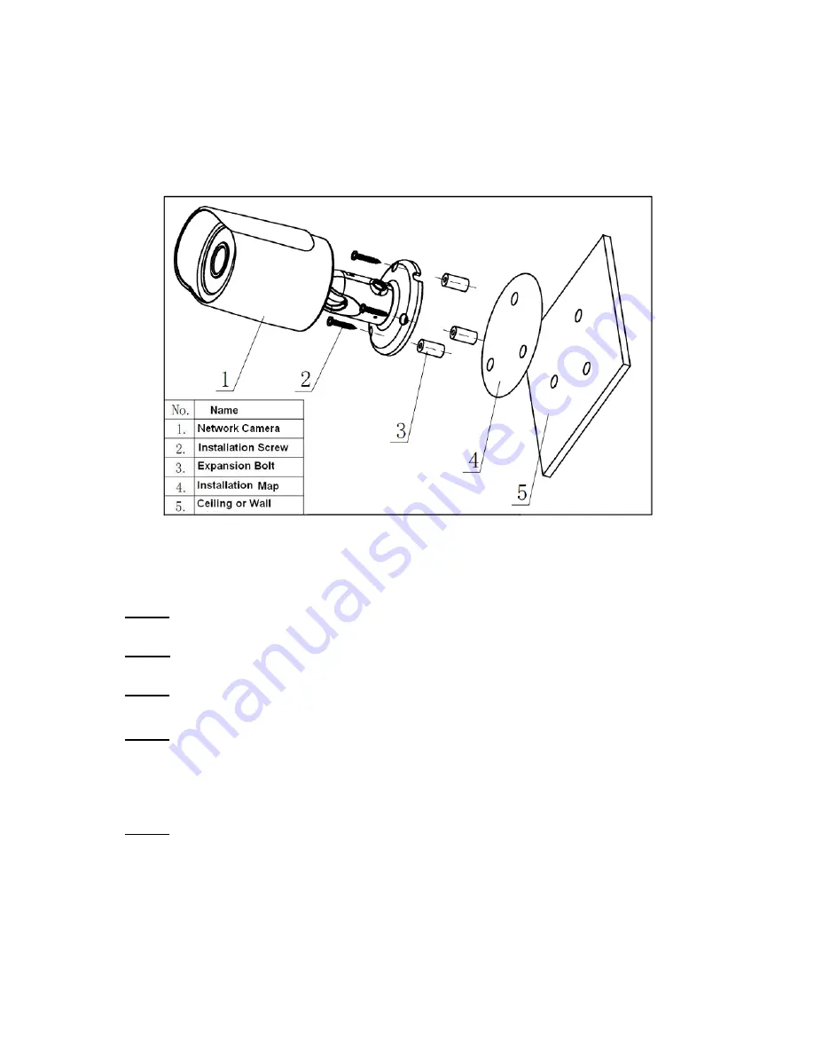
LINOVISION IPC-V3020-IW Quick Start Manual Download Page 9


2


Device Installation  

Important 

Please make sure the installation surface can min support the 3X weight of the camera 

and the bracket.  


Figure 2-1 Device installation 1 


Please see Figure 2-1 and Figure 2-2.


Step 1 

Stick installation map to designated surface where you will install the device (wall or ceiling). 

Step 2  

Dig a hole according to position of hole on installation map. 

Step 3 

Open accessories bag, take out expansion bolt and insert it into the hole you just dug.  

Step 4 

Open accessories bag, take out screws. Tighten the 4 screws to fix the device on the installation 

surface (wall or ceiling). You can move device sunshade back and forth. When you have fixed 

the device, you must tighten screws on sunshade.  

Step 5 

Plug external wiring of the device properly.  

Summary of Contents for IPC-V3020-IW

Page 1: ...HD Mini IR Waterproof Fixed Network Camera Quick Start Guide Version 1 0 0...

Page 2: ...y or responsibility for all the fires or electrical shock caused by improper handling or installation We are not liable for any problems caused by unauthorized modification or attempted repair 2 Envir...

Page 3: ...or hair dries to remove it gently Stained with grease or fingerprint Use soft cloth to wipe the water drop or oil gently to make it dry then use oil free cotton cloth or paper soaked with alcohol or d...

Page 4: ...ser s manual and tool Before installation please open the package and check all the components are included Contact your local retailer ASAP if something is broken in your package Accessory Name Amoun...

Page 5: ...iv Table of Contents 1 Framework 1 1 1 Device External Cable 1 1 2 Framework and Dimension 2 2 Device Installation 4 3 Network Configuration 7 3 1 Modify IP Address 7 3 2 Login WEB Interface 8...

Page 6: ...ble Note Some devices do not support PoE power supply 2 DC 12V Power input port Power port Input DC 12V 3 Reset WPS Reset port WPS Hardware reset wire Press the WPS button of router keep the Reset wir...

Page 7: ...Framework and Dimension The following figures are for reference only which are used to know the device dimension please refer to the following figures according to the actual device Figure 1 3 Figure...

Page 8: ...3 Figure 1 5...

Page 9: ...l the device wall or ceiling Step 2 Dig a hole according to position of hole on installation map Step 3 Open accessories bag take out expansion bolt and insert it into the hole you just dug Step 4 Ope...

Page 10: ...ad screw driver in accessories bag to loosen adjusting screw Step 7 Adjust the device in all possible directions and set its monitoring direction according to the requirements Step 8 Use cross head sc...

Page 11: ...thread of WIFI antenna in the accessories bag at the copper nut on the bottom of the back cylinder Figure 2 4 Step 10 Then bend the antenna in the way shown in Figure 2 4 move the bracket back to the...

Page 12: ...the approach of modifying IP address via Quick Configuration Tool also you can modify the IP address in the network parameters of the WEB interface please refer to the document in the disk WEB Operat...

Page 13: ...nterfaces the figures below are just for reference please refer to the document WEB Operation Manual in the disk and the actual interface for more details Step 1 Open IE and input the modified camera...

Page 14: ...e 3 3 Step 3 Install controls according to the system prompt see Figure 3 4 for the WEB main interface Please modify the administrator password as soon as possible after you successfully logged in Fig...

Page 15: ...ound in user interface All the designs and software here are subject to change without prior written notice If there is any uncertainty or controversy please refer to the final explanation of us Pleas...

Reviews: