7
Chapter 2: Product Overview
Rear-Panel Description
RPS1000—Business Series 380W RPS Unit Installation & Administration
Chapter
2
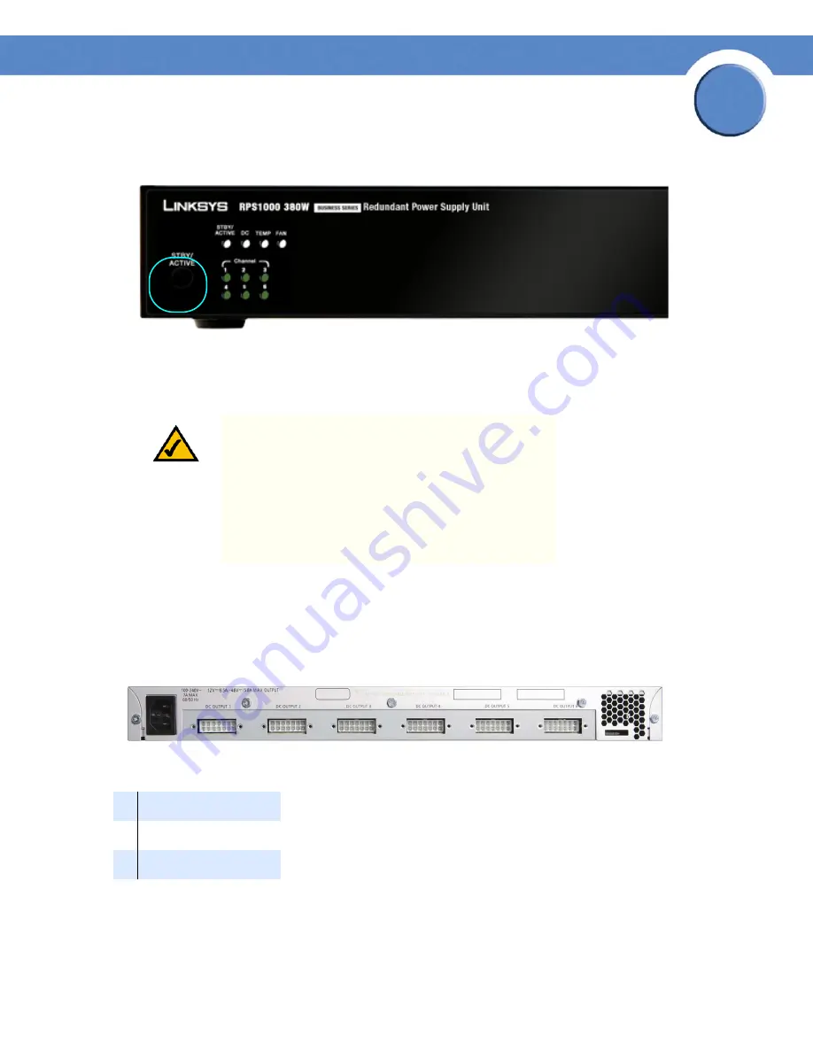
When you want to connect additional devices, press the STBY/ACTIVE button to place the RPS1000
in standby mode. The STBY/ACTIVE LED flashes amber. When you have connected and powered up
all devices, press the STBY/ACTIVE button again to put the RPS1000 into active mode.
Rear-Panel Description
The RPS1000 rear panel has an AC power input connector and six DC output connectors (numbered
1 to 6) to connect to supported devices.
Use the supplied AC power cord to connect to an AC power outlet.
The DC output connectors require a Cisco 16-pin-to-14-pin cable (RPSCBL1) to connect to supported
devices. (One cable is supplied with the RPS1000; you can order additional cables separately.) The
NOTE:
When the RPS1000 is in standby mode, all of the
DC Output LEDs are amber.
NOTE:
When the RPS1000 is in standby mode, the
RPS1000 LED that is on the connected device is amber;
this means that the RPS1000 is connected but is not
functioning. When you press the STBY/ACTIVE button,
the RPS1000 LED that is on the connected device changes
to green to show that the RPS1000 is operating properly.
1
AC input connector
2
DC output connectors
3
Fan exhaust
1
2
2
2
2
2
2
3


