¸
Release 1.0
LINKSYS SFE2000/SFE2000P FAST ETHER
N
ET SWITCH
Linksys SFE2000/SFE2000P Fast Ethernet Switch
Administration Guide
Page 1: ...Release 1 0 LINKSYS SFE2000 SFE2000P FAST ETHERNET SWITCH Linksys SFE2000 SFE2000P Fast Ethernet Switch Administration Guide...
Page 2: ...ubject to change without notice Linksys the Cisco Systems logo the Linksys Logo and the Linksys One logo are registered trademarks of Cisco Systems Inc All other trademarks mentioned in this document...
Page 3: ...Reset Switch 5 LAN Ports 5 Uplink Ports 6 The Back Panel 6 Power Port 7 Console Port 7 RPS Port 7 Chapter 3 Connecting the Switch 8 Overview 8 Before You Install the Switch 8 Placement Options 9 Deskt...
Page 4: ...apter 5 Web Utility Configuration 31 Overview 31 Accessing the Web based Utility 31 Viewing Online Help 31 Appendix A Linksys Contact Information 32 Appendix B Customer Site Survey 34 Appendix C Limit...
Page 5: ...ization and Authentication RADIUS and Terminal Access Controller Access Control System TACACS protocols With Simple Network Time Protocol SNTP the Ethernet switch can synchronize its clock with a time...
Page 6: ...administration guide Chapter 2 Getting to Know the Switch This chapter describes the physical features of the Ethernet switch Chapter 3 Connecting the Switch This chapter explains how to install and c...
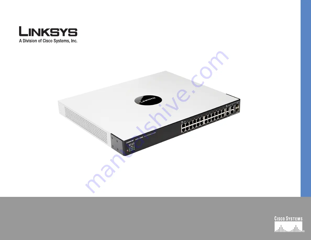
Page 7: ...s of the Ethernet switch power fan RPS connectivity and stack master For more details refer to System Status LEDs on page 4 2 LAN Ports Twenty four 10 100 BaseT LAN ports provide connectivity to other...
Page 8: ...A green MST LED indicates that this Ethernet switch is a stack master Act Link The green Act Link LEDs light to indicate a functional network link through the corresponding port with an attached devi...
Page 9: ...s in the stack LAN Ports The Ethernet switch is equipped with 24 Ethernet ports Stack ID A green Stack ID LED indicates that this Switch is stacked and the corresponding number indicates its stack ID...
Page 10: ...witch provides two mini GBIC ports The mini GBIC port is a connection point for a mini GBIC expansion module so the Switch can be uplinked via fiber or copper to another switch Each mini GBIC port pro...
Page 11: ...PS port An RPS enhances the reliability of the Ethernet switch and it can keep the unit running if a power failure occurs Only use a Linksys RPS1000 Redundant Power Supply unit and a proper RPS cable...
Page 12: ...m sources of electrical noise power lines and fluorescent lighting fixtures Position the Ethernet switch away from water and moisture sources To ensure adequate air flow be sure to provide a minimum c...
Page 13: ...desktop near an AC power source Rack Mount Placement To mount the Ethernet switch in any standard sized 19 inch wide each Ethernet switch requires 1RU of space in the rack follow these instructions 1...
Page 14: ...h 4 Repeat steps 1 through 3 for the other corners of the Ethernet switch 5 Attach the Ethernet switch to a wall with appropriate screws not supplied Connecting the Cables To connect network devices t...
Page 15: ...wer cord to the power port and plug the other end into an electrical outlet 7 Power on the network devices connected to the Ethernet switch Each active port s corresponding Act Link LED will light up...
Page 16: ...e interface in which to control and manage the stack Switch software is downloaded separately for each stack member However all units in the stack must be running the same software version A stack uni...
Page 17: ...ports Connecting Cabling for Stacking When the Ethernet switch is in stacking mode ports G1 G2 copper Gigabit Ethernet ports are reserved as stacking ports and cannot be used as network ports You can...
Page 18: ...lso be performed through the web utility which is covered in the next chapter Configuring the HyperTerminal Application Before you use the console interface you will need to configure the HyperTermina...
Page 19: ...Linksys One Ready Communications Solution Chapter 4 6 On the Connect To screen select a port to communicate with the Ethernet switch 7 Set the serial port settings as follows Bits per second 115200 Da...
Page 20: ...example telnet 192 168 100 21 The Login screen will appear 3 Type the user name and password 4 Press the Enter key Configuring the Switch through the Console or Telnet Interface The management screen...
Page 21: ...ation 4 System Mode Layer 2 Layer 3 Selection 5 Help System Configuration Menu On the System Configuration Menu screen you have these choices 1 System Information 2 Management Settings 3 User Password...
Page 22: ...System Information Use the General System Information screen to display the description System Up Time System MAC Address System Contact System Name and System Location of the Ethernet switch To chan...
Page 23: ...witch To change the baud rate of the serial port a Select Edit to make changes b When your changes are complete press the Esc key to return to the Action menu c Select Save to save your changes Telnet...
Page 24: ...ich the SSH session is enabled To change SSH Server settings a Select Edit to make changes b When your changes are complete press the Esc key to return to the Action menu c Select Save to save your ch...
Page 25: ...s screen lets you specify user names and passwords for the Ethernet switch Up to 5 users can be assigned To change User Password settings a Select Edit to make changes b When your changes are complete...
Page 26: ...o specify a device generated certificate The following fields are specified Public Key Algorithm Specifies the SSL type Public Key Length Specifies the SSL RSA key length Range 512 to 2048 Common Name...
Page 27: ...enu c Select Save to save your changes Show Certificate Use the Show Certificate screen to display the internal certificate Disable Active Management Access Profile Disables the currently active manag...
Page 28: ...orrect and does not conflict with another device on the network Subnet Mask The subnet mask of the Ethernet switch is displayed Default Gateway The IP address of your network s default gateway is disp...
Page 29: ...hanges b When your changes are complete press the Esc key to return to the Action menu c Select Save to save your changes HTTP Configuration The HTTP screen displays the status and port number of the...
Page 30: ...d select Execute to begin the ping test After the ping test is complete the Ping screen displays the IP address status and statistics of the ping test Select Edit to make changes When your changes are...
Page 31: ...change the settings Specify the source and destination of the file the file name and the IP address of the file server where the upgrade file is being downloaded When your changes are complete press t...
Page 32: ...rebooted the Switch Main Menu screen will appear Stack Configuration Select Stack Configuration to specify the Stack ID for the Ethernet switch By default ID numbers are automatically assigned to eac...
Page 33: ...heir status auto negotiation status speed and duplex mode and status of flow control which is the flow of packet transmissions 3 Select Edit to make changes When your changes are complete press the Es...
Page 34: ...switch Your new settings will take effect after reboot Help The Help screen lets you view information about how to navigate the Ethernet switch menus To view help information 1 Select Help 2 Press th...
Page 35: ...e IP address of the Ethernet switch is 192 168 100 20 The IP address of the Ethernet switch is determined by DHCP so you ll need to find its address using the Console configuration or the Linksys One...
Page 36: ...you can e mail us at In Europe E mail Address Austria support at linksys com Belgium support be linksys com Czech Republic support cz linksys com Denmark support dk linksys com Finland support fi link...
Page 37: ...ksys com United Kingdom support uk linksys com Outside of Europe E mail Address Asia Pacific asiasupport linksys com English only Latin America support portuguese linksys com or support spanish linksy...
Page 38: ...ontact information and other information about the customer site that will be needed for the implementation and installation of the Linksys Solution Customer Site Survey Site Name Business Name Site A...
Page 39: ...maintainer of the site Is this a manned site Yes No Hours of Operation Specify the hours of operation for example Monday through Friday 8am to 5pm Saturday 9 am to 12 Noon Number of Users How many us...
Page 40: ...areas Site Coordinator Specify the name and phone number of the site coordinator responsible for ensuring that the site is adequately prepared for the installation of the Cisco equipment Name Phone Ne...
Page 41: ...Linksys pays for UPS Ground shipping from Linksys back to You only Customers located outside of the United States of America and Canada are responsible for all shipping and handling charges ALL IMPLI...
Page 42: ...VISED OF THE POSSIBILITY OF SUCH DAMAGES IN NO EVENT WILL LINKSYS LIABILITY EXCEED THE AMOUNT PAID BY YOU FOR THE PRODUCT The foregoing limitations will apply even if any warranty or remedy provided u...
Page 43: ...ons Operation of this equipment in a residential area is likely to cause harmful interference in which case the user will be required to correct the interference at his own expense Industry Canada Sta...
Page 44: ...igabit combo ports shared between mini GBIC ports Console port Auto MDI MDI X Autonegotiate Manual setting RPS port for connecting to Redundant Power Supply unit Cabling Type UTP CAT 5 or better for 1...
Page 45: ...20 to 70 C 4 to 158 F Operating Humidity 10 to 90 relative humidity Non Condensing Storage Humidity 10 to 95 relative humidity Non Condensing Web User Interface Built in Web UI for easy browser based...
Page 46: ...SSH secure support IEEE 802 1x 802 1x RADIUS Authentication MD5 Hash Guest VLAN Single Multiple Host mode Access Control Drop or Rate Limit based on Source and Destination MAC based Source and Destin...
Page 47: ...ncy QoS Priority levels 4 Hardware queues Scheduling Priority Queuing and Weighted Round Robin WRR Class of Service Port based 802 1p VLAN priority based IPv4 v6 IP Precedence TOS DSCP based Diffserv...
Page 48: ...S 003 Class A EN 55022 Class A CISPR22 Class A EN 55024 EN 50082 1 EN 61000 3 2 EN 61000 3 3 EN 61000 6 1 Dimensions 440 x 375 x 44 mm 17 32 x 14 70 x 1 73 inch W x D x H Unit Weight SFE2000 4 39kg 9...
Page 49: ...45 Appendix E Specifications Linksys One Ready Communications Solution Appendix E...
Page 50: ...2007 Cisco Systems Inc All rights reserved Linksys is a registered trademark and the Linksys One logo is a trademark of Cisco Systems Inc Release 1 0...