


9-port Gigabit Ethernet Switch with 8-port PoE
11
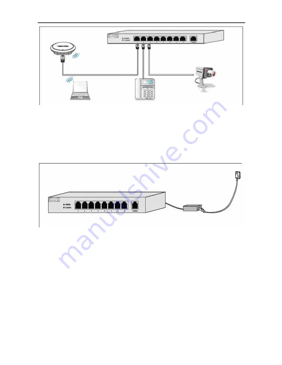
Figure 3-2
Installation with Powered Devices
Step 3:
Use the AC power adapter provided in the product package to supply
power for the switch, shown as Figure 3-3.
Figure 3-3
Installation with the AC power adapter
Step 4:
After powered up, the switch begins auto-initialization. Check the LED
indicators, and they will respond as follows:
All the functional LEDs will flash momentarily for one second and then go off,
which represents a resetting of the system.
The POWER LED indicator is lit.


