iPonic 624® Manual PN 995-1124-00
7| Page
SAFETY WARNING
The iPonic 624 controller supports a maximum of 15 amps at 115 VAC. It is
recommended that the total current for both rooms be no more than 12 amps. To
avoid electric shock, always keep the hinged door closed and locked when the
controller is powered on.
If the total current for the equipment connected to the iPonic exceeds 12 amps,
then external relays/contactors are required. See Appendix B for a suggested
wiring diagram.
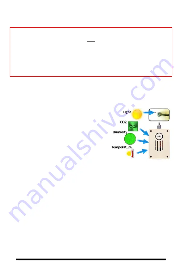
Connect the Indoor Sensor Modules
The iPonic 624 controller comes with two
Digital Integrated Sensor Modules
(DISM) – one for each room.
These sensors measure humidity, temperature,
CO2 and light. It is recommended that you hang
each sensor in a central location within the grow
room facility. Ideally, you want to hang the module
near the crop level and towards the center point of
the controlled environment to produce accurate
readings. You may want to keep the module away
from irrigation emitters, unit heaters, and/or any
other type of equipment that may affect the
accuracy of the sensors.
Securely connect the sensor modules to the plug-in connectors at the bottom of the
iPonic 624 controller. For accurate Light Sensor readings, make sure the Light
Sensor, which is at the top of the DISM module near the cable, is facing upward
and toward the lighting sources in the room. Because of the sensitivity of the
sensors, you may want to experiment with different locations and positions to
determine the best area for getting the most accurate light sensor readings.
Each sensor module comes with a 16-foot cable. You may lengthen and extend the
cables as needed but make sure to use Link4 Extension Cables, Junction Boxes and
wires approved by Link4. Cutting and splicing can result in unstable sensor readings
and failures.
DISM Top View


