Installation Instructions
Chapter6. Installation instructions
6.1. Signal connection
The matrix interface is divided into signal input and output
interface,please use the corresponding cable to connect the input and
output devices, the signal source (such as DVD, computer etc.) output
terminal matrix input device (INPUT), the matrix output (OUTPUT)
connected to the Input interface of signal equipment (such as
projector, TV etc).
6.2. RS232 Communication interface connection
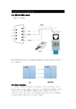
Matrix switch provides a standard RS-232 serial communication
port and RJ45 communication port, users can use a variety of remote
control equipment remote control. The RS-232 port of the matrix is a
D shaped 9 pin male connector (the same as the serial port of the
computer)Pin descriptions are as follows:
Serial
number
Pin
illustration
1
NC
None
2
RXD
Transmit Exchange Data(RXD)
3
TXD
Receive Exchange Data(TXD))
4
NC
None
5
GND
Ground
6
NC
None
7
NC
None
8
NC
None
9
NC
None
Attention: matrix RS-232 port and the computer or the central control,
should pay attention to the TXD and RXD line sequence,specifically to
consider the other device pin definition.
6.3. RJ45 for TCP/IP control
The network matrix is supported by the TCP/IP protocol. When the
matrix is connected to a switch or router or PC directly, the matrix
can communicate. The premise is to keep the IP address of the matrix
and the LAN to be the same segment, otherwise the IP address of the
set matrix should be entered first.


