7
3.3 Installation methods
■
Common hardware items such as nuts, bolts, star washers, lock washers and the like have
not been
evaluated for electrical conductivity or for use as grounding devices and should be used
only for maintaining mechanical connections and holding electrical grounding devices in the proper
position for electrical conductivity. Such devices, where supplied with the module and evaluated
through the requirements in IEC standard, may be used for grounding connections in accordance
with the instructions provided with the module.
■
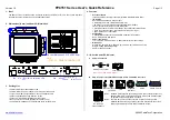
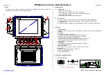
We suggest each module be securely fastened at 8 points (14mm×9mm) with Screw Fitting
Method (Figure 1) using mounting holes or 4 points with Clamping System (Figure 2).
■
Modules must be installed according to the
Module Mounting Guideline
. Failure to
comply may result in damage to modules or detached from the mounting system voiding
the warranty.
■
Module can be installed in both landscape and portrait modes.
■
For best performance, separate laying of positive and negative cables wherever possible.
Induced voltage surges in the DC main cable should be minimized by laying the positive
and negative cables as close together as possible.
•
Where this is not possible or not desirable, the inverter energy system should
be connected to the distribution board located physically nearest to the inverter,
and the main switchboard. And main switch for the switchboard, to which the
inverter is connected, shall be a lockable switch.
■
The modules must be properly secured to their support so that they can withstand live load
conditions, including wind uplift, to the pressure they have been certified for. It is the
installer's responsibility to ensure that the clamps used to secure the modules are strong
enough.


