〇ᢶࡑ᯦䘳≸উ䏀KWWSZZZOLQJMLDQJFRP
䈊ؑ
࣑ᇎ
ࡋᯠ
ቭ䍓
-14-
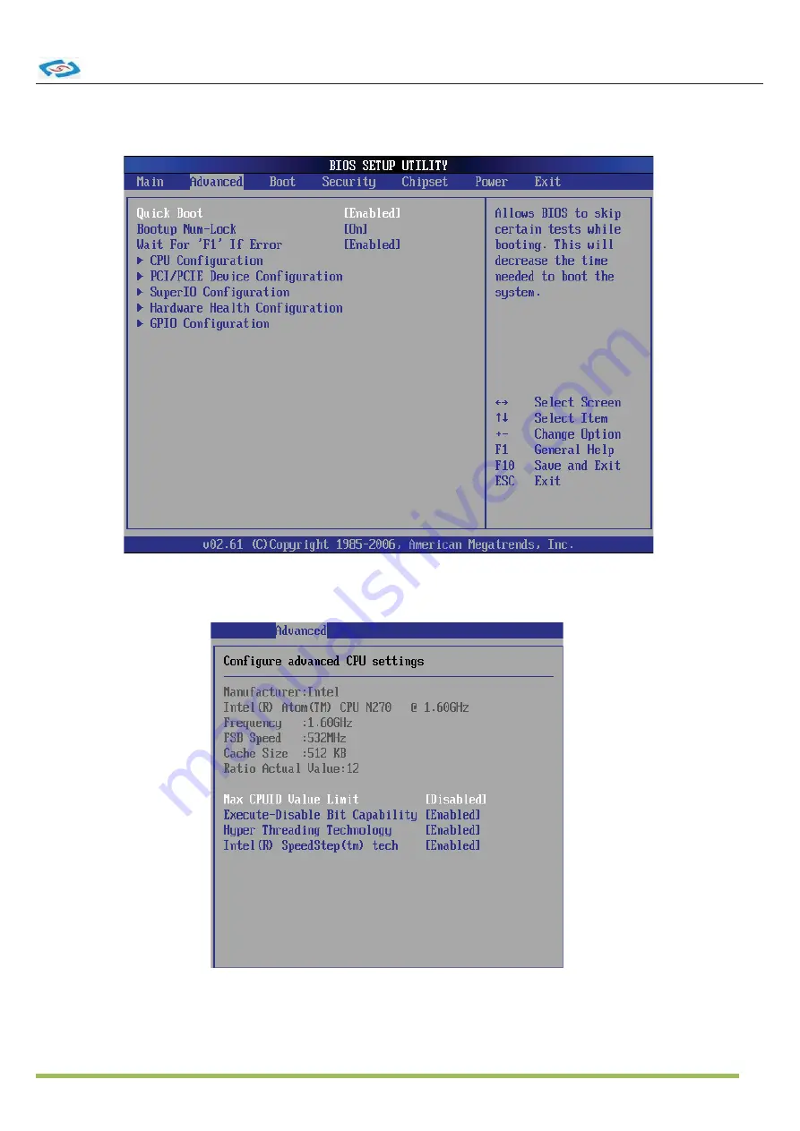
3.3 Advanced
)
CPU Configuration
Page 1: ...LBOX 270...
Page 2: ...photocopy manual or otherwise 2ther brands and product names used herein are for identi cation purposes only and may be trademarks of their respective owners Disclaimer from the performance or use of...
Page 3: ...nding circuit Make sure that your power supply is set to the correct voltage in your area If you are not sure about the voltage of the electrical outlet you are using contact your local power company...
Page 4: ...II 5 SO DIMM 8p to 2 B Display Integrated Intel MA 50 Fx Core in 5 S MC ATA 1 x Serial ATA port with 150MB s DD transfer rate LAN Chipset Watchdog 1 a 255 level reset Serial Port 8SB Port x 8SB 2 0 po...
Page 5: ...ative umidity 10 a 5 0 C non condensing 9ibration MIL STD 10F Method 51 5 Procedure 1 Category Shock Crash Operating 20 11ms Non Operating 0 with DD Operating 0 11ms Non Operating 0 with SSD Crash 100...
Page 6: ...the slot and insert the DIMM into the slot at 45 degree angle 2 Push the DIMM gently forwards until the slot levers click and lock the DIMM in place Follow the same procedures to install the second DI...
Page 7: ...ED Right LED Active LED 100M 1000 Speed LED LED Color Yellow Green Orange 10M Cable Plug in No Transmission OFF OFF Transition Yellow Blinking OFF 100M Cable Plug in No Transmission OFF Green Lighting...
Page 8: ...2 RXD Receive Data 3 TXD Transmit Data 4 DTR Data Terminal Ready 5 GND Signal Ground 6 DSR Data Set Ready 7 RTS Request To Send 8 CTS Clear To Send 9 VCC_COM1 Voltage output voltage select setting by...
Page 9: ...KWWS ZZZ OLQJ MLDQJ FRP 10 2 1 System Introduction 2 System Installation...
Page 10: ...ems under each BIOS category described in this chapter are under continuous update for better system performance Therefore the description may be slightly dif ferent from the latest BIOS and should be...
Page 11: ...sts the setup functions you can make changes to You can use the arrow keys to select the item The on line description of the highlighted setup func tion is displayed at the bottom of the screen Sub Me...
Page 12: ...k PIO Mode Indicates the type of PIO Programmed Input Output DMA Mode Indicates the type of Ultra DMA S M A R T This allows you to activate the S M A R T Self Monitoring Analysis Reporting Technology...
Page 13: ...KWWS ZZZ OLQJ MLDQJ FRP 14 3 3 Advanced CPU Configuration...
Page 14: ...lication code can execute and where it cannot When a malicious worm attempts to insert code in the buffer the processor disables code execution preventing damage or worm propagation Hyper Threading Te...
Page 15: ...nboard USB controller USB 2 0 Controller This setting enables disables the onboard USB controller Audio Controller This setting enables disable the onboard USB controller LAN Option ROM The items enab...
Page 16: ...llow BIOS to Select Serial Port1 Base Address Select Screen Select Item Change Field Tab Select Field F1 General Help F10 Save and Exit ESC Exit V02 61 C Copyright 1985 2006 American Megatrends Inc CO...
Page 17: ...h Configuration GPIO Configuration These items display the current status of all monitored hardware devices components such as voltages temperatures and all fans speeds GP 60 61 62 63 64 65 66 67 Data...
Page 18: ...OS attempts to load the disk operating system Try Other Boot Devices Setting the option to Enabled allows the system to try to boot from other device if the system fail to boot from the 1st 2nd 3rd bo...
Page 19: ...Password User Password controls access to the system at boot These settings allow you to set or change the user password Boot Sector Virus Protection This function protects the BIOS from accidental c...
Page 20: ...es whether to force the LVDS inactive or not DVMT FIXED Memory When set to DVMT FIXED Mode the graphics driver will allocate a xed amount of memory as dedicated graphics memory as well as allow more s...
Page 21: ...eld Tab Select Field F1 General Help F10 Save and Exit ESC Exit V02 61 C Copyright 1985 2006 American Megatrends Inc Enable Disable ACPI support for Operating System ENABLE If OS supports ACPI DISABLE...
Page 22: ...ystem will be awadened from power saving modes when activity or input signal of onboard LAN is detected Resume On PME When setting to Enabled the feature allows your system to be awakended from the po...
Page 23: ...the Setup Utility Discard Changes Abandon all changes and continue with the Setup Utility Load Optimal Defaults Use this menu to load the default values set by the mainboard manufacturer speci cally f...
Page 24: ...sor X87 Unit 170h 177h Secondary IDE 1F0h 1F7h Primary IDE 200h 22Fh GAME I O 220h 22Fh Sound Blaster AD Lib 279h A79h Plug and Play Configuration Register A15h A16h HW Monitor Access Port 2E8h 2EFh C...
Page 25: ...b g n WiFi it Optional 8 16GB MLC Type SSD Optional 5 1 Packing List 2 Power adapter 3 Mounting bracket 4 1 GB DDRII SO DIMM Memory Optional 5 2 GB DDRII SO DIMM Memory Optional 6 2 5 160GB Hard Disk...