4
dc2023afa
DEMO MANUAL DC2023A
Quick start proceDure
The following procedure describes how to set up a DC2023A
demo system.
1. Download and install the LTpowerPlay GUI:
http://www.linear.com/ltpowerplay
2. Remove the board from the ESD protective bag
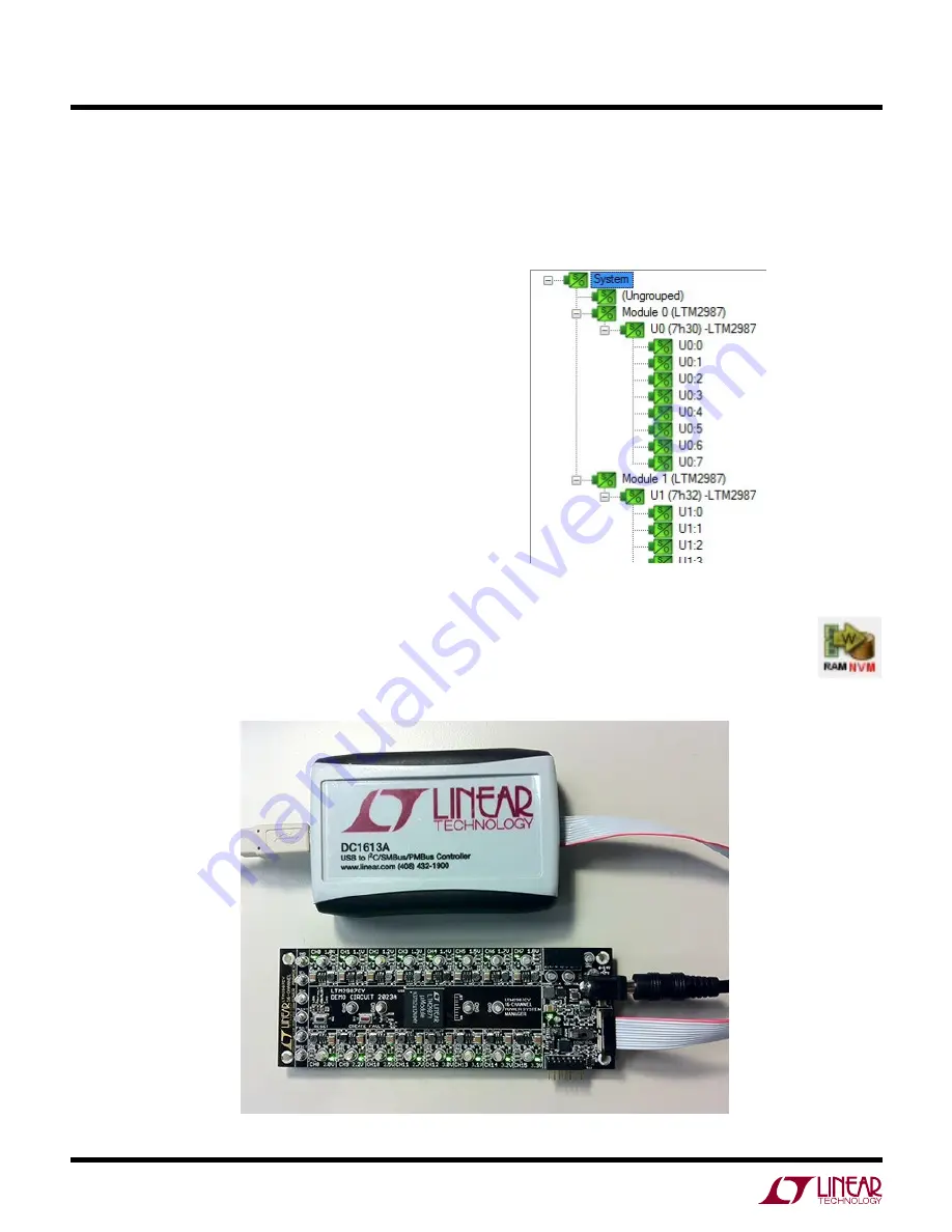
and place it on a level surface. Connect the DC1613
I
2
C/SMBus/PMBus Controller to the DC2023A board
using the 12-pin ribbon cable.
3. Confirm that the CONTROL switch is set to the RUN
position.
4. Plug the USB to I
2
C/SMBus/PMBus Controller into a
USB port on your PC. The board should power up with
all power good LEDs and +5V LED illuminated green.
The USB-to-I
2
C/SMBus/PMBus Controller supplies
~100mA of current which should be sufficient for a
single demo board.
5. If multiple boards are being powered, connect a +12VDC
power supply with > 0.5A capacity to the V
IN
input jack
of the DC2023A.
6. Launch the LTpowerPlay GUI.
a. The GUI automatically identifies the DC2023A and
builds a system tree. The system tree on the left hand
side should look like this:
Figure 2. Connecting DC2023A board and the DC1613 I
2
C/SMBus/PMBus Controller
Note: For multiple board arrays, the GUI automatically
ensures each device has a unique address. In this
scenario, it is recommended at this point to
store these addresses to NVM (EEPROM)
by clicking the “RAM to NVM” icon in the
toolbar.


