8
dc2313af
DEMO MANUAL DC2313A
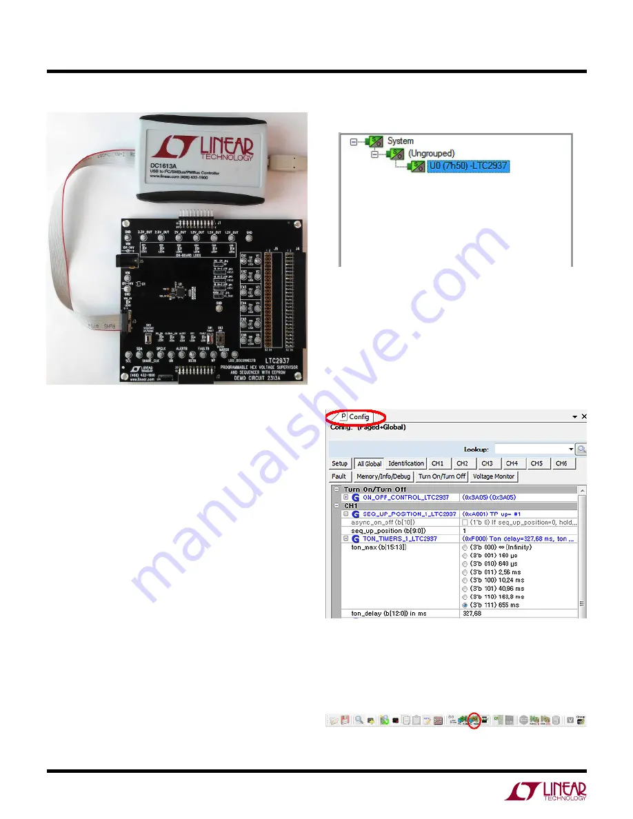
The DC1613 USB-to-I
2
C adapter interfaces the PC running
LTpowerPlay to the DC2313A board (or any board with an
I
2
C bus). Connect the DC1613 adapter to the PC through a
USB cable, and connect it to the DC2313A board through
the ribbon cable to connector J3.
Launch the LTpowerPlay GUI on the PC. The software
identifies the DC1613 controller, then the DC2313A board,
and begins communicating through the I
2
C bus with the
LTC2937. Once this communication has been established,
the GUI displays its main window (Figure 5).
The LTpowerPlay GUI divides information into separate
panes in the window. On the left is the System Tree pane,
displaying a list of all Linear Technology devices identified
on the I
2
C bus. For a single LTC2937 device, the tree is
small, but if other supported devices are present on the
I
2
C bus, LTpowerPlay will add them. Click on a device in
this list to selectively access it. Information in other panes
pertains to the selected device.
software controL with LtpowerpLay
Figure 4. DC2313A Demo Board Connected
to DC1613A I
2
C-to-USB Converter
lTpowerPlay System Tree
lTpowerPlay Configuration Registers
To the right of the system tree is the Configuration Register
pane, displaying all of the configuration registers avail-
able on the selected device. This view shows all of the
writable user-configurable RAM registers, and the GUI
offers clickable buttons and fields to edit the information
in these registers.
Update register contents by clicking or typing to change
the desired registers, then selecting the “Write All” but-
ton in the top toolbar. LTpowerPlay writes changes to the
updated registers.


