QUICK START GUIDE FOR DEMONSTRATION CIRCUIT 1016
5V TRIPLE HIGH SPEED VIDEO AMPLIFIER
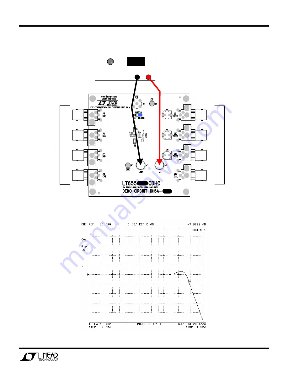
3
COM +
Power Supply
+5.00
Inputs
Outputs
5V-7.5V
Figure 1.
Recommended Demo Circuit Setup
Figure 2.
Typical Transmission Frequency Response
Page 1: ... into High impedance 6dB nominal Outputs terminated into 75Ω 6dB nominal Gain B version Outputs terminated into High impedance 0dB nominal VIN 125mVPP 16dBm 3dB RL 75Ω 7Hz to 380MHz typical Frequency Response VIN 125mVPP 16dBm 0 1dB RL 75Ω 7Hz to 130MHz typical Worst case All Hostile 10MHz 75dB typical Crosstalk Worst case All Hostile 100MHz 55dB typical Input Signal Voltage Range 5 0V Supply No O...
Page 2: ...and connector effects to be eliminated from the transmission measurements Figure 4 shows the material list of the components used by DC1016 and Figure 5 shows the electrical intercon nection QUICK START PROCEDURE Demonstration Circuit 1016 is easy to set up to evaluate the performance of the LT6557 or LT6558 Refer to Figure 1 for proper measurement equipment setup and follow the procedure below NO...
Page 3: ...RT GUIDE FOR DEMONSTRATION CIRCUIT 1016 5V TRIPLE HIGH SPEED VIDEO AMPLIFIER 3 COM Power Supply 5 0 0 Inputs Outputs 5V 7 5V Figure1 Recommended Demo Circuit Setup Figure2 Typical Transmission Frequency Response ...
Page 4: ...CUIT 1016 5V TRIPLE HIGH SPEED VIDEO AMPLIFIER 4 0 1 2 3 4 5 0 2 4 6 8 10 12 14 16 18 20 TIME nS OUTPUT V VIN 1Vp p VS 5V RL 150Ω Ω Ω Ω TA 25 C Figure3 Typical Time Domain Transmission Response Figure4 DC1016 Bill of Material A version shown ...
Page 5: ...QUICK START GUIDE FOR DEMONSTRATION CIRCUIT 1016 5V TRIPLE HIGH SPEED VIDEO AMPLIFIER 5 Figure5 DC1016 Electrical Schematic Diagram ...