MODEL BGUS/BGUS-D
•
SG/SG-D OPERATOR INSTALLATION GUIDE
-14-
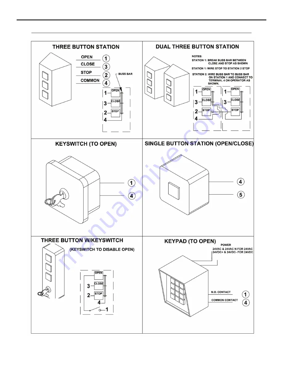
CONTROL and ACCESSORY CONNECTION ILLUSTRATIONS
Page 1: ...UIDE BGUS BGUS D SG SG D Operator models contained in this manual conform to UL325 standard for use in Class I II III and IV applications USA Canada 800 421 1587 800 392 0123 760 438 7000 Toll Free FA...
Page 2: ...11 Auto Close Timer Adjustment 11 Master Slave Connection 11 Onboard L E D Indicator Descriptions 12 Surge Protector Instructions 12 BGUS D and SG D Charger Board Sleep Mode 13 Control and Accessory...
Page 3: ...requirements for all four classifications Read the following before beginning to install LINEAR barrier gates 1 All electrical connections to the power supply must be made by a licensed electrician an...
Page 4: ...round wire must be properly connected 7 Wire insulation must be suitable to the application 8 Control wiring must be run in a separate conduit from power wiring Running them together may cause interfe...
Page 5: ...out EL drawing for proper positioning of your gate 5 With a pencil mark the location of the mounting holes on the concrete 6 Set the gate aside Drill all four mounting holes using a 3 4 diameter rotar...
Page 6: ...FOR MODEL BGUS BGUS D 1 Make sure the barrier gate is in the full closed position 2 With someone s assistance lift the arm 2 up to a height even with the barrier gate flange 3 Using the hardware 3 pr...
Page 7: ...up to a height even with the barrier gate flange The far end should either be supported by something of equal height as the flange or be held by someone throughout the next steps 4 Assemble the wood...
Page 8: ...LATION Gear reducers used in LINEAR gate operators will have pinned vent plugs installed prior to shipping in order to keep the oil from spilling out during transportation During installation this pin...
Page 9: ...is used in conjunction with single button controls and radio receivers In the ON position successive inputs will cause signals in the order of OPEN STOP CLOSE STOP In the OFF position inputs will caus...
Page 10: ...operator to raise and stay open until the signal is gone at which point the arm will immediately begin to come down 4 51 CLOSE This function works only while the arm is coming down Any signal to this...
Page 11: ...gate operator stops and reverses again From this point turn the close direction potentiometer higher by 1 1 2 turns for all 115 Volt AC and 24 Volt DC operators and by 3 4 of a turn higher for all 23...
Page 12: ...right hand operator or the open 1 on a left hand If this indicator is lit and the gate is not in its full open closed position the limit may need adjusting or the limit switch may need replacing Moto...
Page 13: ...ndby time the charger board has a sleep mode feature which will turn off power to all controls except for any that are wired according to the schematics below By removing the black jumper cap JP1 loca...
Page 14: ...MODEL BGUS BGUS D SG SG D OPERATOR INSTALLATION GUIDE 14 CONTROL and ACCESSORY CONNECTION ILLUSTRATIONS...
Page 15: ...MODEL BGUS BGUS D SG SG D OPERATOR INSTALLATION GUIDE 15 CONTROL and ACCESSORY CONNECTION ILLUSTRATIONS...
Page 16: ...MODEL BGUS BGUS D SG SG D OPERATOR INSTALLATION GUIDE 16 CONTROL and ACCESSORY CONNECTION ILLUSTRATIONS...
Page 17: ...the gate stops and the stop button must be pressed to reset gate C An obstruction signal from an accessory wired to the obstruction input may have triggered falsely Check the control board for lit L E...
Page 18: ...MODEL BGUS BGUS D SG SG D OPERATOR INSTALLATION GUIDE 18 MODEL BGUS MECHANICAL PARTS EXPLODED VIEW...
Page 19: ...15 Hex Nut 3 8 16 31 2400 017 Flat Washer 3 8 Ref Part No Number Description 32 2400 182 Wing Nut 10 32 33 2200 314 Set Collar 1 1 4 34 2400 474 Roll Pin 3 8 x 1 x 2 35 2400 043 Star Washer 10 36 2400...
Page 20: ...MODEL BGUS BGUS D SG SG D OPERATOR INSTALLATION GUIDE 20 MODEL BGUS D MECHANICAL PARTS EXPLODED VIEW...
Page 21: ...2400 474 Roll Pin 3 8 x 1 x 2 35 2400 043 Star Washer 10 36 2400 032 Hex Nut 10 32 37 2400 049 Screw 8 32 x 3 8 self tap 38 2500 029 Limit Switch 40 2400 246 Screw 6 32 x 2 1 4 Pan Head 42 2400 069 Ke...
Page 22: ...MODEL BGUS BGUS D SG SG D OPERATOR INSTALLATION GUIDE 22 MODEL SG MECHANICAL PARTS EXPLODED VIEW...
Page 23: ...ucer Double Pulley 7 22 2200 918 Intermediate Pulley 2 2 required 23 2200 151 V Belt 25 2 required 24 2200 235 Motor Pulley 1 5 8 25 2200 011 Pulley 6 2 required 28 2200 208 V Belt 26 2 required 33 22...
Page 24: ...MODEL BGUS BGUS D SG SG D OPERATOR INSTALLATION GUIDE 24 MODEL SG D MECHANICAL PARTS EXPLODED VIEW...
Page 25: ...ey 6 2 required 28 2200 208 V Belt 26 2 required 33 2200 314 Set Collar 1 1 4 34 2400 474 Roll Pin 3 8 x 2 38 2500 764 Limit Switch 43 2300 028 Limit Cam 50 2400 238 Key 3 16 x 3 16 x 1 1 4 60 2200 22...
Page 26: ...rm 1 x 6 x 16 2 required 2 2100 496 Wood Extension Arm 1 x 6 x 10 3 2400 108 Screw 3 8 16 x 3 hex head 4 2400 017 Flat Washer 3 8 5 2400 016 Lock Washer 3 8 2400 015 Hex Nut 3 8 16 7 2400 418 Nylon Lo...
Page 27: ...with AC Motor Drive Board 9 2520 444 Limit Switch Harness Assembly 10 2510 249 Input Wire Harness Assembly 11 2510 250 Output Wire Harness Assembly 12 2510 261 Control Box Motor Harness Assembly 13 25...
Page 28: ...20 444 Limit Switch Harness Assembly 10 2510 249 Input Wire Harness Assembly 11 2510 250 Output Wire Harness Assembly 13 2500 071 Terminal Strip 16 141 2 14 2510 261 Control Box Motor Harness Assembly...
Page 29: ...t The motor has two brushes one on each side Original brushes are approximately 3 4 long and should be replaced when they are 1 4 long or sooner If brushes are allowed to wear beyond this point perman...
Page 30: ...ear and replace as necessary Check for proper tension and adjust if required Check all pulley setscrews for tightness and tighten if necessary 3 For operators with internal chain drives inspect chain...
Page 31: ...sions near the source Laboratory samples should be handled in a fume hood Provide mechanical ventilation of confined spaces HANDLING STORAGE AND SHIPPING Keep containers closed Handle and open contain...
Page 32: ...USA Canada 800 421 1587 800 392 0123 760 438 7000 Toll Free FAX 800 468 1340 www linearcorp com 5 19 2009 P686 X3 Copyright 2009 Linear LLC...