QUICK START GUIDE FOR DEMONSTRATION CIRCUIT 518
SLIC POSITIVE INPUT TO NEGATIVE OUTPUT DC/DC CONVERTER
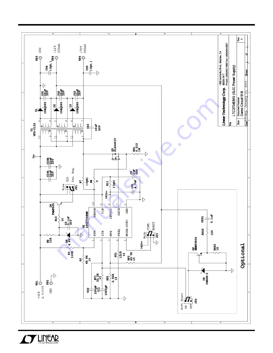
5
Page 1: ...re available Call the LTC factory Table 1 Performance Summary PARAMETER CONDITION VALUE Minimum Input Voltage 4 5V Maximum Input Voltage 15V VOUT1 VIN 5V to 15V IOUT1 0A to 0 2A 24V 3 VOUT2 VIN 5V to...
Page 2: ...4V and VOUT2 70V If there is no output temporarily disconnect the load to make sure that the load is not set too high 5 Once the proper output voltage is established adjust the load within the operati...
Page 3: ...serve the switching frequency of 200kHz 6 Turn the clock source ON and observe the switching frequency go up to the switching frequency of the external clock USING NO RSENSE MODE OF OPERATION 1 No Rse...
Page 4: ...ion of RS1 2 Connect the center conductor of the coaxial cable to the RS1 terminal that is connected to the source of MOSFET Q1 Use a 50 surface mount resistor in series with the center conductor 3 Se...
Page 5: ...QUICK START GUIDE FOR DEMONSTRATION CIRCUIT 518 SLIC POSITIVE INPUT TO NEGATIVE OUTPUT DC DC CONVERTER 5...