5
dc1705afa
DEMO MANUAL DC1705A
QUICK START PROCEDURE
DC1705A Configuration
1. Connect an appropriate reference frequency source (at
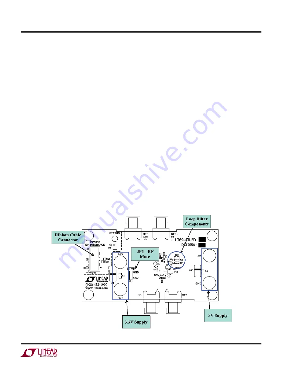
J1) and signal analyzers (at J4 and/or J5) using the
SMA connectors (see Figure 1 and the Typical DC1705A
Requirements and Characteristics table).
2. Choose the
MUTE
jumper setting:
JP1 - GND/3.3V
MUTE
position. Select GND to mute the RF output, 3.3V to
un-mute.
3. Connect the GND, 3.3V and 5V banana jacks to a power
supply and apply power (see Figure 1 and the Typical
DC1705A Requirements and Characteristics table).
4. Connect the DC590 to the DC1705A with the provided
ribbon cable.
5. Run the PLLWizard application.
6. In PLLWizard, click File
→
Load Settings and point to
the appropriate pllset file. For example, if you are using
a 10MHz reference with a DC1705A-B to evaluate the
LTC6946-2, load the “DC1705A-B (LTC6946-2) 10MHz
Ref.pllset” file found in the PLLWizard installation direc-
tory (typically Program Files
→
LTC
→
PLLWizard
→
Set Files).
The red LED on DC1705A should turn on indicating that
the loop is locked at 900MHz.
You can then change the values of N_DIV and/or O_DIV
in PLLWizard to change the output frequency.
Troubleshooting
If the red LED does not illuminate, follow the instructions
below:
1. Verify that you are able to communicate with the
DC1705A. The bottom status line in PLLWizard should
read “LTC6946” and “Comm Enabled.” Refer to PLL-
Wizard’s Troubleshoot and Help if not.
2. Verify that the 3.3V and 5V have the correct voltages
on them and that the reference frequency is applied to
the REF
+
IN SMA input.
If the red LED is on but you cannot detect an RF output,
make sure jumper JP1 is at the 3.3V position. Run Help
→
Troubleshoot in PLLWizard if the problem is not resolved.
DC1705A Reconfiguration
You can redesign the frequency plan of the DC1705A using
PLLWizard. You can change the loop filter components
as found using PLLWizard by reinstalling the loop filter
components shown in Figure 4.
Figure 4. DC1705A Components and Connections


