
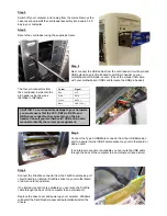

Step 2
Switch off your computer, and unplug from the mains. Remove the
case cover and install the card reader assembly into a spare 5.25“
bay in your computer
Step 3
Secure the card reader using the supplied screws
Step 4
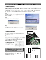
Next, connect the USB cables from the card reader circuit board and
USB extension port circuit board to a USB pin header on your
motherboard or USB add-on card. (Check the manual that came
with your motherboard / USB card to locate the USB pin header)
Colour Signal
Red VCC
White DATA
-
Green DATA
+
Black GND
(VCC-)
The four pin connectors from
the card reader install onto the
pin header using the wires
identified in this table:
CAUTION: To avoid possible damage to your hardware
you must ensure that the VCC, DATA+, DATA- and
GND wires connect to the correct pins on the pin
header. Consult your motherboard / USB add-on card
manual to identify the correct pin assignment.
Step 5
Connect the Type A USB Male connector from the USB Extension
port to a spare internal USB Female socket on your motherboard or
add-on card.
If no internal connection is available you can route the USB cable
through the back of the computer to an external port (see picture)
Step 6
Connect the FireWire connector from the FireWire extension port
circuit board to an internal FireWire socket on your motherboard
or add-on card (see picture).
If no internal connection is available you can route the FireWire
cable through the back of the computer to an external port.
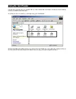
Replace the case cover and power up your computer. Windows
will detect the Card Reader panel and automatically install the
drivers.


