Lindy 25051 User Manual Download Page 11


                              11 

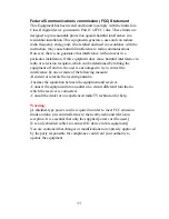
Federal Communications commission (FCC) Statement 

This Equipment has been tested and found to comply with the limits for a 
Class B digital device, pursuant to Part 15 of FCC rules. These limits are 
designed to pro reasonable protection against harmful interference in a 
residential installation. This equipments generates, uses and can radiate 
radio frequency energy and, if not stalled and used in accordance with the 
instruction, may cause harmful interference to radio communications. 
However, there is no guarantee that interference will not occur in a 
particular installation. If this equipment does cause harmful interference to 
radio or television reception, which can be determined by turning the 
equipment off and on, the user is encouraged to try to correct the 
interference by one or more of the following measure: 
-Reorient or relocate the receiving antenna. 
-Increase the separation between the equipment and receiver. 
-Connect the equipment into an outlet on a circuit different from that to 
which the receiver is connected. 
-Consult the dealer or an experienced radio/TV technician for help. 
 

Warning: 

[A shielded-type power cord is required in order to meet FCC emission 
limits and also prevent interference to the nearby radio and television 
reception. It is essential that only the supplied power cord be used.] 
[Use only shielded cables to connect I/O device to this equipment.] 
You are cautioned that changes or modifications not expressly approved 
by the party responsible for compliance could void your authority to 
operate the equipment. 


Summary of Contents for 25051

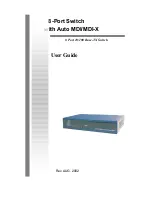
Page 1: ...8 Port Switch with Auto MDI MDI X 8 Port 10 100 Base TX Switch User Guide Rev AUG 2002...

Page 2: ...detect the speed of the device that you plug into it to allow you to use both 10 and 100Mbps device They feature a store and forward switching and it can auto learn and store source address on an 1K e...

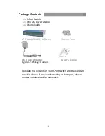
Page 3: ...s Guide 8TP Auto MDI MDI X Switch Rubber Feet DC power Adapter User s Guide Figure 1 2 Package Contents Compare the contents of your 8 Port Switch with the standard checklist above If any item is miss...

Page 4: ...witch are the same 164mm W X 100mm D x 26mm H Front Panel The LED indicators are located on the frond panel of the Switch They provide a real time indication of systematic operation status The Front P...

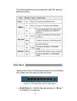
Page 5: ...ection LED Status Color Description Power On Green The power of the Switch is On On Green The port is connecting with 100Mbps 100Mbps Off The connection between the Switch and the device is 10Mbps if...

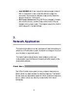
Page 6: ...Network Application This section provides you a few examples of network topology in which the 8 Port Switch is used the Switch is design to be used as a desktop or segment switch The switch automatic...

Page 7: ...hed workgroup to form a large switched network You can connect anyone switch port to hub or switch without crossover cable by the Auto MDI MDI X function In the below illustration two Switches are use...

Page 8: ...8 Figure 3 2 Example of enlarging your network...

Page 9: ...he proper cable type is used and its length does not exceed specified limits Power IF the power indicator does not turn on when the power cord is plugged in you may have a problem with power outlet or...

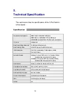
Page 10: ...s Ethernet port 148 800 pps per Fast Ethernet port LED Indicators Per Port Link Activity Full Collision 100M Per Unit Power Network Cables 10Base T 2 pair UTP Cat 3 4 5 cable 100m EIA TIA 568 100 ohm...

Page 11: ...be determined by turning the equipment off and on the user is encouraged to try to correct the interference by one or more of the following measure Reorient or relocate the receiving antenna Increase...

Reviews: