LBON820ACT Series 1.2 GHz 8-Port OBI-Free RFoG ONU (Fiber to the Tap - FTTT)
INSTALLATION MANUAL
Page 3 of 4
OPTICAL, RF & POWER CONNECTIONS
1.
The powering port and all RF ports are standard F-type coaxial connectors.
2.
Power input to the ONU is either 40-90 VAC HFC power or 100-240 VAC mains power. Use the included power adapter to power this ONU when using 100-240
VAC mains power. There is no power passing ability in this ONU.
3.
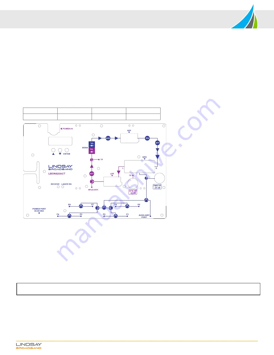
The port labeled “POWER PORT” is for powering the ONU. The F connector ports labeled “P1” to “P8” are subscriber ports 1 to 8. Refer to Figure 1.
4.
The F connector port labeled “AUXILIARY PORT” connects to a co-located multitap to service up to additional 8 subscribers. Recommended practice is to
completely set up the node and then connect a tap to the auxiliary port to connect more subscribers.
5.
The auxiliary port has 13 dB higher RF level than the subscriber ports. Choose a multitap plate value such that there will be sufficient RF level to serve each
subscriber location.
6.
Connect coaxial cables to each port of the ONU. Make sure all unused F ports are terminated.
7.
The optical connector is located in the lid. Make sure the optical cable is matched for proper connection. i.e. SC/APC to SC/APC.
8.
The ONU accepts optical input of 1550 ± 10 nm and optical levels from -6 dBm to +2 dBm. Using an optical power meter make sure the optical level is within range.
9.
After cleaning all optical connectors, connect optical fiber.
10.
Turn ON the ONU by applying power. When the ONU is turned ON, the LED display will turn ON. And the “RECEIVE” LED will either be lit
GREEN
,
ORANGE
or
RED
based on the optical input level. Refer to the table below.
Optical Input Level
-8 dBm to +2 dBm
< -8 dBm
> +2 dBm
Receive LED
GREEN
ORANGE
RED
Figure 1
SETUP
1.
When the LBON820ACT is powered up, the LED display will initialize. The Optical Receive and Laser ON LEDs will turn ON based on the input level. The LED
display will turn OFF after 5 minutes of inactivity. Press any button to turn ON the LED display.
2.
There are 3 pushbuttons for set up and adjustment. Up/Down buttons to navigate through the menu and change values. Press the ENTER button to adjust any
parameter value. Press and hold Enter for 3 seconds to adjust any parameter.
3.
See Figure 2 for the setup menu flowchart.
4.
When the LED display turns ON the first parameter displayed under menu
1
is the Received Optical Input power. Confirm if the displayed value is close to the
expected input value (-6 dBm to +2 dBm). If not then unplug the fiber and check using an optical power meter.
5.
Press the UP pushbutton to check through other parameters of the ONU. Under the menu
2
&
3
values of 8 V & 12 V voltage rails are displayed.
6.
The
A
G
setting is the AGC optical range setting. You can set the low end of the optical AGC range from -5 dBm to -8 dBm. The high end remains the same for all
settings (i.e. +2 dBm). When a lower optical AGC range is chosen other than -6 dBm, the RF output will drop 2 dB with every 1 dB drop in AGC range. For eg: the
system is designed such that with -6 to +2 dBm AGC range and 3.5% OMI optical input; the ONU will deliver 25 dBmV output per port. If you change the low end of
AGC range from -6 dBm to -7 dBm, then the output will drop to 23 dBmV per port. With -8 dBm range setting, output will be 21 dBmV per port.
7.
Next set the
E
forward start frequency or diplex filter parameter. Set the value to
54
for 42/54 MHz,
11
0
for 85/102 MHz;
258
for 204/258 MHz diplex filter. The
diplex filter set is field-replaceable and it consists of 3 filters. A low pass filter, a high pass filter and a low/high DPX diplex filter. Make sure to plug in all 3 filters to
ensure proper performance and set the diplex filter parameter to appropriate value.
8.
Check the RF output using a signal level meter at any of the subscriber ports. It should be 25 dBmV per port with 3.5% OMI and optical input in AGC -6 to +2 dBm
spec. The output from the auxiliary port will be 38 dBmV. If all subscriber ports are occupied, you can also check the RF output at the FWD -20 dB TP. The forward
TP is a bi-directional -20 dB test point relative to the auxiliary port. Levels from this test point are -20 dB relative to the auxiliary port and only -8 dB relative to the
subscriber ports. Therefore, output at FWD TP will be 17-18 dBmV.
9.
With the menu
E
1
&
A
1
you can set the forward equalization and forward attenuation respectively. Max value that can be set is 20 dB.
10.
The forward path setup is now complete.
NOTE: Please note that the RF levels mentioned anywhere in this manual are analog channel levels. For digital channels assume 6 dB less to that
of analog channels.


