10/21
Linde AG, Linde Gas Deutschland ©
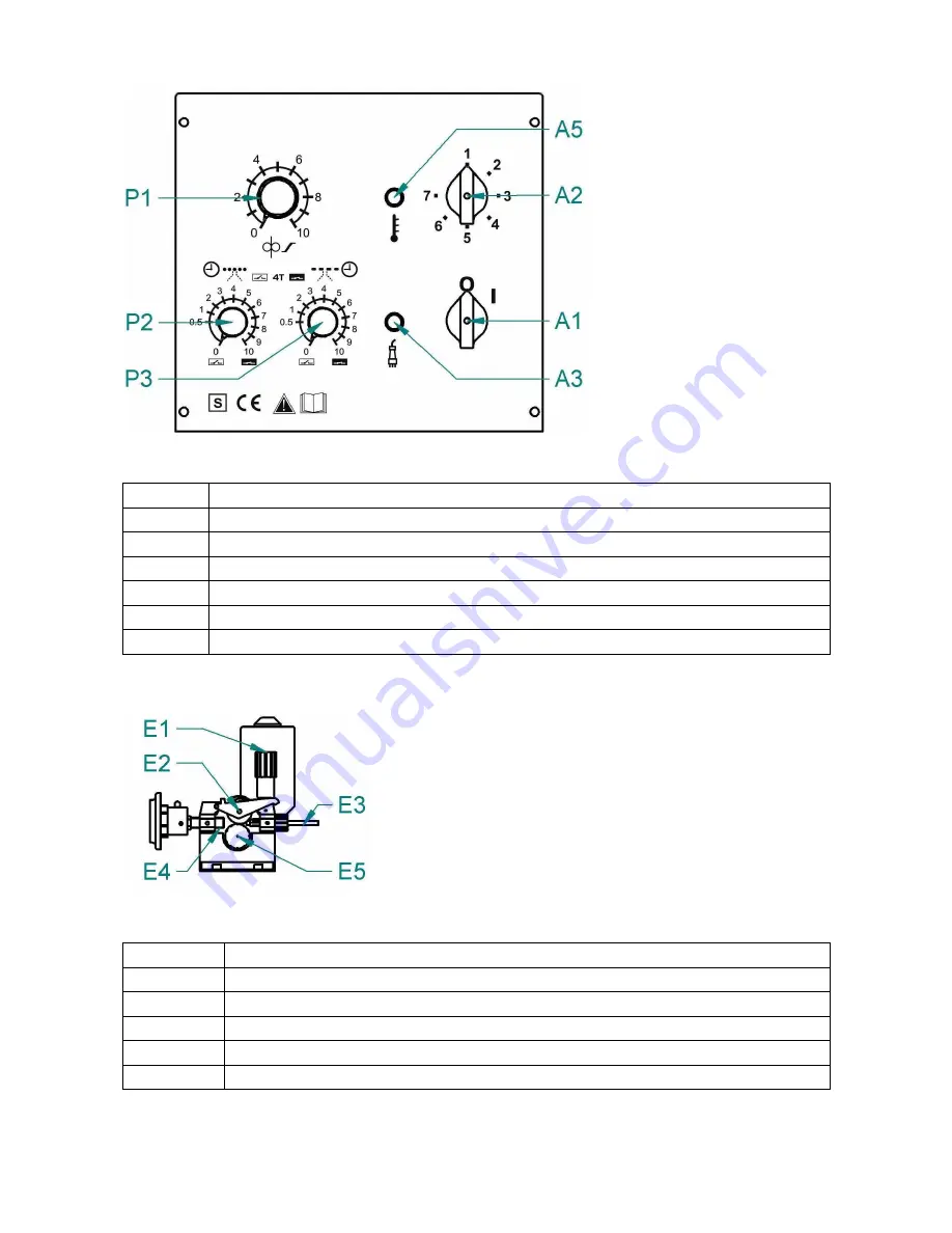
CONTROL PANEL - OVERVIEW
Fig. 2 - Control panel
A1
PCB - encoder ON / OFF Switch
A2
Voltage switch
A3
LED ON Indicator
A5
LED over heating indicator
P1
Wire speed potentiometer
P2
Spot time potentiometer
P3
Interval time potentiometer
WIRE FEEDER
Fig 3 – Wire feeder
Pos.
Description
E1
Fixing shaft
E2
Pressure arm
E3
Liner- Feeder
E4
EURO connector
E5
Roll, Plastic cup


