background image

   23

12.0 Cutting Technique

12.1 Cutting

As a general rule for cutting amperages below 40 A 

the cutting tip can be dragged on the cutting surface. 

Higher amperages require a stand-off distance and 

torch manufacturers normally supply a stand-off 

guide or ‘drag shield’. Some operators prefer to use an 

extended electrode to improve visibility when cutting. 

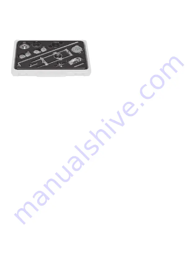
BOC supplies guides that can be purchased to assist in 

straight line, circular and bevel cutting.
For straight edge cutting the torch should be held at 

a 90° angle to the plate and dragged along the plate 

(Refer to Diagram 1). The cutting speed will depend 

on the material thickness, amperage and airflow rate.
For bevel cutting the torch should be angled on the 

plate to the required bevel angle and dragged on the 

plate surface. (Note that the bevel angle will influence 

the material thickness).

12.2  Piercing and Gouging

To pierce material the cutting torch should be held 

at an angle of 45° to the pierce surface (Refer to 

Diagram 2). Once the arc is established the torch 

is turned to 90° (Refer to Diagram 3) and cutting is 

carried out in a normal manner. Piercing thickness 

is dependent on the output of the machine and is 

generally 50% of the rated cutting thickness of the 

power source.

It is important to direct the arc away from the 

operator when establishing the arc as sparks and 

molten material will be ejected from the point of 

contact. Care must also be taken to protect the 

surrounds from these sparks.

When gouging with plasma it is advisable to 

use a plasma gouging tip supplied by the torch 

manufacturer. The torch should be held at an angle of 

40–45° from the plate surface (Refer to diagram 4). 

An arc length of up to 15 mm can be employed whilst 

the torch is moved in the direction of the material to 

be removed. Several small cuts should be made to 

remove the unwanted material.

Typical Plasma Cutting Guide Kit  

Summary of Contents for BOC Raptor CUT 30C

Page 1: ...CUT 30C Operating Manual 2 2 y e a r conditional wa r r a n t y 2 y e a r conditional war r a n t y...

Page 2: ...ission which may become apparent after the document has been issued Neither BOC nor any of its agents has independently verified the accuracy of the information contained in this document The informat...

Page 3: ...e Regulator 15 6 2 Attaching the Plasma Torch 15 6 3 Setting up the power source 15 7 0 Operating Controls 16 8 0 Operating Connections 17 9 0 Machine Specifications 18 10 0 Plasma Cutters 19 10 1 Fun...

Page 4: ...rch or wiring can kill Wear dry insulating gloves Do not wear wet or damaged gloves Protect yourself from electric shock by insulating yourself from work and ground Disconnect input plug or power befo...

Page 5: ...nd constant observation are essential Leads and cables should be kept clear of passageways Keep fire extinguishing equipment at a handy location in the shop Keep primary terminals and live parts effec...

Page 6: ...fined space cutting should be carried out with the aid of a fume respirator or air supplied respirator as per AS NZS 1715 and AS NZS 1716 Standards You must always have enough ventilation in confined...

Page 7: ...glasses Ensure cylinder value is closed before moving or disconnecting equipment Before operating a cylinder valve Ensure that the system you are connecting the cylinder into is suitable for the gas...

Page 8: ...rator and will void your warranty Only qualified personnel approved by BOC should perform repairs Always disconnect mains power before investigating equipment malfunctions Parts that are broken damage...

Page 9: ...y current I1eff I1 2 X I0 2 1 X The I1eff determines the correct plug input cable and input current required for each machine 10A I1eff I1eff I1eff I1eff 1 5 2 5mm2 min max cable size size must be ind...

Page 10: ...ng machines undergo an independent certification process to meet Australian and New Zealand regulations regarding electrical safety The triangle circle tick RCM symbol signifies that BOC has taken the...

Page 11: ...ensure that you have the correct input circuit to support this power draw What if I don t have a 240volt 15amp or 32amp outlet If you don t have a suitable power outlet you should contact a qualified...

Page 12: ...12 3 0 Package Contents Assembly 3 1 Package Contents Power source Air filter assembly Plasma torch PCH 35 style Work return lead Operating manual 3 2 Installing Adjustable Shoulder Strap 1 2 3 4...

Page 13: ...ing the torch to the power source 1 Fit torch connection A to connection point on machine indicated as Screw torch connection in firmly but do not overtighten 2 Fit the work return lead and clamp to t...

Page 14: ...breakdown and cutting consumables Description Part No Smoothcut Plasma 40 Torch 6m BOC40 706HTC 1 Electrode BOC9 6506 2 Gas distributor BOC9 6507 3 Cutting tip 20 40A BOC9 6500 4 Shield cup BOC9 6003...

Page 15: ...ing screw till correct air pressure is achieved 6 2 Attaching the Plasma Torch 1 Attach the plasma torch to the machine torch connector outlet 2 Attach the work return lead and connector to the machin...

Page 16: ...16 1 1 2 2 4 4 3 3 Control Panel 1 Thermal overload Indicator 2 Power light 3 Amperage control Knob 4 Gas post flow control Knob 7 0 Operating Controls...

Page 17: ...30C Back Connections of Raptor Cut 30C 1 Torch connector 2 Work return lead connector 3 Air Pressure Adjustment Knob 4 Mounting Bracket 5 Air Inlet Connector 6 Pressure Indicating Dial 7 Moisture trap...

Page 18: ...output current range 12 5 40A Output voltage range 96V Duty cycle 15 Efficiency 84 Power factor 0 72 Insulation grade F Housing protection grade IP21 Arc initiation Contact Air pressure requirement 3...

Page 19: ...on back Air compressor sold seperately Work lead and connector Main power supply Plasma Torch Workpiece Amperage control knob Torch connector Air supply hose Power On Off switch on back 10 0 Plasma C...

Page 20: ...asting through thicker metals and blowing away the cuttings leaving minimal cleanup 10 2 Process Operation Compressed air flows through the torch A pilot arc is established inside the head of the plas...

Page 21: ...A Three phase 50 35 20 11 3 Air Supply The supply of air to the cutting process plays an important role The force of the air is used to blow the molten material created by the plasma arc away from the...

Page 22: ...t cleaning is required Highly portable and relatively low cost to set up Versatility Highly versatile stack cutting of material and combinations of different materials can be cut No additional gas cyl...

Page 23: ...hickness 12 2 Piercing and Gouging To pierce material the cutting torch should be held at an angle of 45 to the pierce surface Refer to Diagram 2 Once the arc is established the torch is turned to 90...

Page 24: ...24 Diagram 1 90 Cutting Direction Diagram 3 Diagram 4 Diagram 2 90 45 Gouging Direction 40 45...

Page 25: ...n situations of up to 90 relative humidity 2 It is designed to work in ambient temperature range of between 10 to 40 C 3 Avoid cutting in sunshine or wet showers Do not let water enter the gas airflow...

Page 26: ...wer voltage departs from the rated value it will cause the output to not achieve its set value 5 Electrode or nozzle easily damaged 1 Current is too high or using wrong size nozzle 2 Air pressure is l...

Page 27: ...t limited to daily allowances or accommodation and travelling costs Modification of the 10A primary input plug or fitment of a lower rated primary input plug will render the warranty null and void NOT...

Page 28: ...28...

Page 29: ......

Page 30: ......

Page 31: ......

Page 32: ...t proper care has been taken in the preparation no liability for injury or damage resulting from its improper use can be accepted BOC Limited ABN 95 000 029 729 10 Julius Avenue North Ryde NSW 2113 Au...

Reviews: