background image

26

2018-08-01

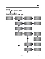
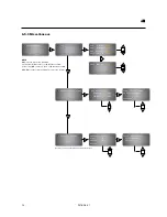
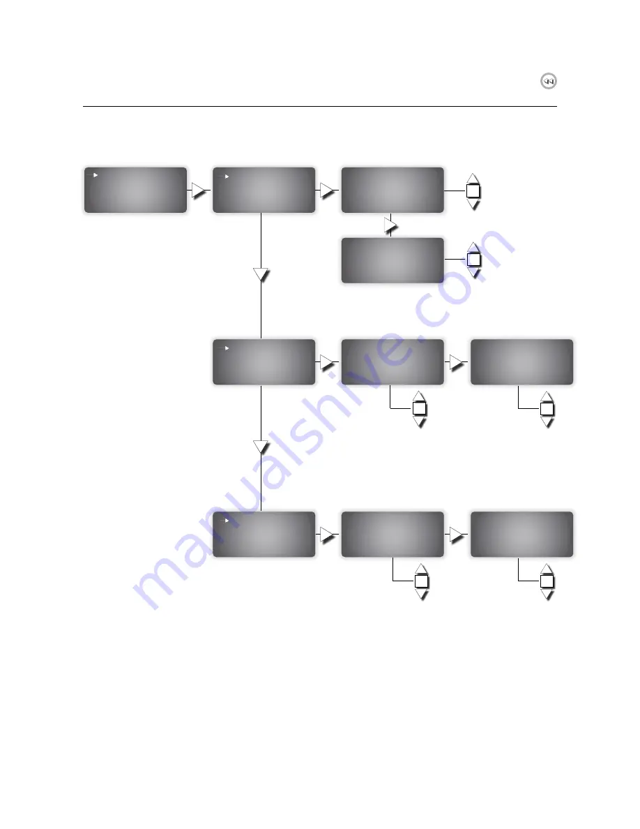
6.5.9 Miscellaneous

    Miscellaneous
 

    I/O


OK

DO5   Status:  

NO/NC

DO6   Status:  

NO/NC

DO7   Status:  

NO/NC

EXT1  Status:  

NO/NC

EXT2  Status:  

NO/NC

OK

    Damper Durat. times


 Max durat. time:
   Opening:  

180 

sec

   Closing:  

60  

sec

Save current times
as orig. times?

Confirm: 

NO

    Detector values


OK

OK

Detector Limits
High:   

9.5 

V

Smoke:  

6.0 

Dirty:  

4.0 

V

OK

Synch. parameters
  Synchronize: 

NO

  Confirm    : 

NO

OK

NOTE


DO5 is for the interaction with AHU.  
If using FDS-B (NC contact), set DO5 status on NC. 
If other relay (NO contact) is used, set DO5 status on NO.

DO6-DO7 contact set depending on logic of the system.

In order to change sensitivity of smoke detectors

Summary of Contents for FDS-CD

Page 1: ...lindab we simplify construction User manual Lindab Fire Damper Steering System Version 1 2 August 2018...

Page 2: ...slave unit to slave unit 12 4 4 Connect signal repeater to slave unit 14 5 External signals 5 1 External incoming alarms 15 5 2 External outgoing alarms 15 5 3 Connect Stop AHU signal 16 5 4 Configura...

Page 3: ...ktor Airflow Luftfl de Airflow Luftfl de 1 FDS P 10 FDS S 10 WH WK 10 FDS CD DD If the communication cable is more than 300 m a signal repeater FDS R is required This is also required if the number of...

Page 4: ...units it can provide 10 FDS S Depending on cable and lenght It is required if more than 30 slave dampers are con nected to the system or if the communication cable is longer than 300 m FDS RB Relay m...

Page 5: ...ter unit is a pre programmed controller with internal display The display is backlit and the menus are easy accessible and controlled by pushbuttons on the front together with two LED indicators for a...

Page 6: ...cation or dirty smoke detector 3 Steady red A fire alarm Fig 4 Slave unit Fig 5 Internal PCB about FDS S The internal PCB allows to connect one fire damper power supply two position switches and one s...

Page 7: ...1 S4 S2 S6_1 S1 S6 C S2_2 S4 S2 S6_2 S1 S6 Fire damper 2 C S2_3 S6_3 C S2_4 1 2 Power supply 0 230V 0 24V B A G G0 Slave unit A B Master unit FDS M Smoke detector L1out L1in L2 2 2 k Ceiling smoke de...

Page 8: ...M Smoke detector 5 3 4 2 2 k Duct smoke detector 1 2 FDS M G0 D01 G0 D02 G0 D03 G0 D04 Fire damper 1 1 2 Fire damper 2 FDS M C S2_1 Fire damper 1 S4 S2 S6_1 S1 S6 C S2_2 S4 S2 S6 S1 S Fire damper 2 1...

Page 9: ...DS P Supply power to the first slave unit through G0 and G pins Connect the signal from master unit FDS M to A and B pins 0 24V 0 230V 4 Installation with slave unit If in the system there are slave u...

Page 10: ...DS S A B G G0 FDS S A B 1 2 FDS S 4 5 3 6 8 7 1 2 Fire damper S1 S6 S2 S4 5 6 1 2 FDS S 4 5 3 6 8 7 Smoke detector L1out L1in L2 7 2 2 k Ceiling smoke detector 1 2 FDS S 4 5 3 6 8 7 Smoke detector 5 3...

Page 11: ...nit is allowed 1 2 Fire damper S1 S6 S2 S4 6 1 2 FDS S 4 5 3 6 8 7 Smoke detector L1out L1in L2 7 2 2 k Ceiling smoke detector 1 2 FDS S 4 5 3 6 8 7 Smoke detector 5 3 4 2 2 k Duct smoke detector 1 2...

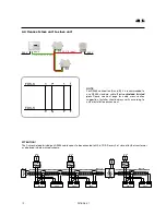
Page 12: ...pair Please see next page for cable cross section suggestion Installer should always verify according to actual installation environment RS485 A B N A B A B FDS S G G0 230 VAC 24 VAC 230 V A B FDS S G...

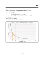
Page 13: ...ccepted voltage drop 2V in the cable V I is the current A L is the longest distance of supply cables from transformer to a component m Example Udrop 2V I 4A L 20m R per m 2V 4A 20m 0 025 m In the diag...

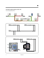
Page 14: ...cation 2 input 230 V 230 V 24 V 2 input no 30 FDS S 230 V 230 V 3 8 G G0 FDS S B A G G0 FDS S B A DATA0 DATA0 FDS R DATA1 DATA1 L N FDS M C Ext1 10 Ext2 Ack FDS M GD0 A 11 D06 S D07 Data Data FDS S FD...

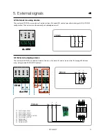
Page 15: ...send no 2 external alarms a fire alarm A and a service alarm S through 24V driven relays relay module FDS RB NC contact 3 8 DATA0 DATA0 FDS R L N FDS M C Ext1 3 10 Ext2 Ack FDS M GD0 A 3 11 D06 S D07...

Page 16: ...FDS M 34 connect with slave units FDS S AHU connection External outgoing fire alarm FDS M FDS S FDS P FDS R FDS RB 1 34 4 1 2 if the logic NO or NC is different between connections AHU and external ou...

Page 17: ...the system can be Idle Normal operation Test procedure OK C OK view alarms exit value editing Yellow LED write indicator Red LED Alarm indicator Scroll up Scroll down Enter right Confirm one step back...

Page 18: ...r level automatically change status depending on type of password entered 6 3 Main display tree After the first LOG IN press to show the main display tree Access right Status Commissioning Settings Ev...

Page 19: ...ector 1 Det Status OK Det Alarm No Section status DI I O Section status Section 1 Status OK Damper 1 6 DI1 OFF DI5 ON DI2 ON DI6 OFF DI3 OFF DI7 OFF DI4 ON DI8 OFF UI1 OFF UI2 ON UI3 OFF UI4 ON DO DO1...

Page 20: ...s Choose damper unit 1 60 Damper unit 1 Duration Times Close Open 8 23 sec Reset detector s Detector 0 0 means all Reset NO Reset detectors Damper unit 1 Orig Dur Times Close Open 7 25 sec AO AO1 0 0...

Page 21: ...ressing means that number of damper and its IP address are automatically assigned to the system in sequence by pressing the right button in the FDS S as described below ATTENTION Dampers connected to...

Page 22: ...ove ADRESSMODE from YES to NO Automatic addresmode Address Mode NO OK 6 5 3 Manual addressing Manual addressing mode means that number of damper and its IP address are manually assigned to the user by...

Page 23: ...ble to connect locally single smoke detector to FDS M unit without any fire damper OK 6 5 5 Sections Fire dampers smoke detectors can be grouped into sections Sections Sections divider Section 1 OK Se...

Page 24: ...nning DNS 0 0 0 0 MainComputer Status Not connected Activate connection to Main Computer NO Activate connection to Main Computer NO TCP port routing to Main Computer 1 EXOline address PLA 1 ELA 241 DN...

Page 25: ...Activate YES Speed 9600 bps Parity NO 6 5 7 Activate Deactivate System In ACTIVATE SYSTEM mode Activate Activate sys YES Confirm YES In DEACTIVATE SYSTEM mode Deactivate Deactivate sys NO Dampers open...

Page 26: ...ave current times as orig times Confirm NO Detector values OK OK Detector Limits High 9 5 V Smoke 6 0 V Dirty 4 0 V OK Synch parameters Synchronize NO Confirm NO OK NOTE DO5 is for the interaction wit...

Page 27: ...Status Commissioning Settings Language Language English Excecise operation Interval timer Timer Enabled Test delay time Choosen time 12 00 Due in 39 22 hh mm Test Exercise Test delay time Weekly time...

Page 28: ...onfirm NO Damper test Test delay time Test all dampers Test ind damper NOTE Please see Text Excercise display on previous page Manual operation Oper all dampers Oper all dampers Oper AUTO Confirm NO N...

Page 29: ...29 2018 08 01 6 7 Event log Event log Alarm events Use and to scroll up and down the list of alarm events A alarm fire alarm and Service alarm are listed in the Event log display...

Page 30: ...ilability and logistics We are also working on ways to reduce our impact on our environment and climate We do that by de veloping methods to produce our solutions using a minimum of energy and natural...

Reviews: