background image

10 


Ékszíjas meghajtású, olajkenésű, dugatt


 LINCOS Slovenia 


STD-3550 

Two Post Lift - Electrical Release 

6. 

Press LOCK button to make the lift in safe condition then perform 
maintenance or repair work. 

B)  LOWERING THE LIFT 

1. 

Clean all the obstacles before lowering the vehicle. 

2. 

Press the down button and the carriage will raise up a little, then go down. 

3. 

Release your finger when vehicle lowered to the height you want. 


5  MANINTENANCE 

We  will  give  the  user  one-year  warranty  of  quality  for  the  machine.  If  something 
wrong  with  the  machine  within  the  term  of  service,  we  will  repair  or  replace  the 
product  according  to  the  user’s  demand.  The  manufacturer  will  not  take  any 
responsibility  for  improper  installation  and  operation,  overload  running,  wrong 
concrete  ground  (that  cannot  meet  the  requirements  in  the  manual),  normal 
mechanical  abrasion  and  insufficient  maintenance.  The  warranty  will  be  carried  out 
on  the  basis  of  the  type  and  serial  number  of  the  equipment.  Therefore,  the  users 
shall provide them to the manufacturer without fail. 
 
The several pieces of maintenance operations to be carried out are described below. 
A  low  operating  cost  and  a  long  life  of  the machine  are from  routine  observation  of 
there operations. 
 
The  listed  intervention  times  are  given  for  information  and  they  refer  to  normal 
operating conditions. They can change according to the kind of service, environment, 
frequency of use, etc. 
 

5.1  DAILY PRE-OPERATION CHECK 

The  user  should  perform  daily  check.  Daily  check  of  safety  latch  system  is  very 
important  the  discovery  of  device  failure  before  needed  could  save  you  from 
expensive  property  damage,  lost  production  time,  serious  personal  injury,  even 
death. 

  Check safety lock audibly and visually while in operation. 

  Check hydraulic connections, and hoses for leakage. 

  Check chain connections, cable connections, wiring and switch for damage. 

  Check bolts, nut and screws and tighten. 

  Check swing arm restraints. 


5.2  WEEKLY MAINTENANCE 


  Check the cleanness of the mobile parts. 

  Check the safety device as previously described. 

Summary of Contents for STD-3550

Page 1: ...t Lift Electrical Release STD 3550 TWO POST LIFT WITH ELECTRICAL RELEASE LINCOS d o o CELOVŠKA CESTA 492 SI 1000 LJUBLJANA TEL 386 31 390 850 EMAIL shop lincos si WEB www lincos si LOAD 5500 kg Max hoist height 1900 mm Min hoist height 100 mm Raising time 50 s Voltage 230V ...

Page 2: ...s Failure to comply with the safety instructions may result in injury to the operator or people nearby as well as damage to the machine or workpiece It is essential to observe the safety instructions and safety labels on your machine Never remove them If damaged replace the labels TABLE OF CONTENT SAFETY INSTRUCTIONS 3 WARNING SIGNS 4 1 INTRODUCTION 5 2 TECHNICAL DATA 5 3 INSTALLATION 6 3 1 TOOLS ...

Page 3: ...to lift the entire body of vehicle having maximum weight not more than the lift capacity 9 Always ensure the safety devices are engaged before any attempt to work on or near vehicle 10 The vehicle must be centred and positioned in a stable correct way with respect to the posts and following the instruction given by manufacturer 11 Make sure that the machine and its devices are working correctly ac...

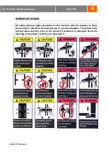
Page 4: ...lease WARNING SIGNS All safety warning signs presented on the machine with the purpose to draw the operator s attention from dangerous or unsafe situations The labels must be kept clean and they have to be replaced if detached or damaged Read the meaning of the labels carefully and memorize it ...

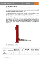
Page 5: ...rolley is equipped inside each column The lift is operated by an electric motor controlling a hydraulic pump which delivers the hydraulic fluid to cylinders inside the columns for lifting two trolleys The 2 post lift is suitable for lifting motor vehicles having maximum weight as described below any other use is to be considered improper and irrational and thus highly forbidden the constructor can...

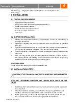
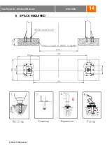
Page 6: ...5m from anchoring points 4 The lift installation concrete surface must be relatively smooth levelled in all directions 5 After unloading the lift place it near the intended installation location Remove the shipping brands and packing materials from the unit Remove the packing brackets and bolts holding the two columns together SPACE REQUIRED Please refer to the drawing for detailed installation si...

Page 7: ...EE MOUNTING THE OVERHEAD BEAM FOR CLEARFLOOR LIFT 1 Using a lifting device to raise the overhead beam into position on top of the columns Bolt the beam to columns with bolt and nut and washer supplied with the product STEP FOUR MOUNTING POWER UNIT SAFETY DEVICE and CONTROL BOX 1 Attach the power unit to the main column with supplied tools and parts Fill the reservoir with hydraulic oil 2 Mount the...

Page 8: ...aise and lock each carriage approximately 800mm high above the ground 2 Make sure that the safety locks on each column are fully engaged before attempting to route equalizer cables 3 Carriages must be equal height from the floor before proceeding 4 With the carriages in equal position from the floor route the equalizer cables as shown 5 After the equalizer cables have been routed adjust each cable...

Page 9: ... of automobile is not within the supporting range of the supporting device Otherwise the manufacturer will not bear any responsibility for the consequence resulted from the operation above mentioned d The staff or operators shall be in a safe position when the machine lift or lower e Raise and lower several times to make sure no air in the cylinder Air inside of the cylinder makes raising not smoo...

Page 10: ... the type and serial number of the equipment Therefore the users shall provide them to the manufacturer without fail The several pieces of maintenance operations to be carried out are described below A low operating cost and a long life of the machine are from routine observation of there operations The listed intervention times are given for information and they refer to normal operating conditio...

Page 11: ...on each time he restarts work 6 TROUBLE SHOOTING MOTOR DOES NOT RUN A Breaker or fuse blown Replace it B Motor thermal overload tripped Wait for overload to cool C Faulty wrong connections Call electrician for checking D Defective up button Call electrician for checking MOTOR RUNS BUT WILL NOT RAISE A A piece of trash is under check valve Push handle down and push the up button at the same time Ho...

Page 12: ...Power unit if the power unit leaks hydraulic oil around the tank mounting flange check the oil level in the tank The level should be two inches below the flange of the tank Check with a screwdriver B Rod end of the cylinder The rod seal of the cylinder is out Rebuild or replace the cylinder C Breather end of the cylinder the piston seal of the cylinder is out Rebuild or replace the cylinder LIFT M...

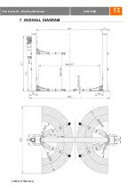
Page 13: ...13 Ékszíjas meghajtású olajkenésű dugatt LINCOS Slovenia STD 3550 Two Post Lift Electrical Release 7 OVERALL DIAGRAM ...

Page 14: ...14 Ékszíjas meghajtású olajkenésű dugatt LINCOS Slovenia STD 3550 Two Post Lift Electrical Release 8 SPACE REQUIRED ...

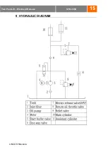
Page 15: ...15 Ékszíjas meghajtású olajkenésű dugatt LINCOS Slovenia STD 3550 Two Post Lift Electrical Release 9 HYDRAULIC DIAGRAM ...

Page 16: ...enia STD 3550 Two Post Lift Electrical Release 10 HYDRAULIC CONNECTING 1 Main Cylinder 2 Assist Cylinder 3 Hydraulic Hose 4 Cylinder Joint 5 Cylinder Joint 6 Bonded Washer 7 Hose Joint 8 Cylinder Hose 9 Fix Joint 10 Pump Hose 11 Pump Joint 12 Power Pack ...

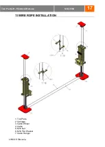
Page 17: ...szíjas meghajtású olajkenésű dugatt LINCOS Slovenia STD 3550 Two Post Lift Electrical Release 11 WIRE ROPE INSTALLATION 1 Top Plate 2 Carriage 3 Cable Wheel 4 Cable 5 M16 Nut 6 M16 Flat Washer 7 Cable Hanger ...

Page 18: ...18 Ékszíjas meghajtású olajkenésű dugatt LINCOS Slovenia STD 3550 Two Post Lift Electrical Release 12 WIRING DIAGRAM ...

Reviews: