


D-1
MAINTENANCE
D-1
VISUAL INSPECTION
Clean interior of machine with a low pressure air
stream. Make a thorough inspection of all compo-
nents. Look for signs of overheating, broken leads or
other obvious problems. Many problems can be
uncovered with a good visual inspection.
ROUTINE MAINTENANCE
1. Every 6 months or so the machine should be
cleaned with a low pressure airstream. Keeping
the machine clean will result in cooler operation
and higher reliability. Be sure to clean these areas:
•
All printed circuit boards
•
Power switch
•
Main transformer
•
Input rectifier
•
Auxiliary Transformer
•
Reconnect Switch Area
2. Examine the sheet metal case for dents or breakage.
Repair the case as required. Keep the case in good con-
dition to insure that high voltage parts are protected and
correct spacings are maintained. All external sheet
metal screws must be in place to insure case strength
and electrical ground continuity.
PERIODIC MAINTENANCE
Overload Protection
The machine is electrically protected from producing
high output currents. Should the output current
exceed 430A, an electronic protection circuit will
reduce the current to approximately 100A. The
machine will continue to produce this low current until
the protection circuit is reset. Reset occurs when the
output load is removed.
Thermal Protection
Thermostats protect the machine from excessive
operating temperatures. Excessive temperatures may
be caused by a lack of cooling air or operating the
machine beyond the duty cycle and output rating. If
excessive operating temperature should occur, the
thermostat will prevent output voltage or current. The
meter will remain energized during this time.
Thermostats are self-resetting once the machine cools
sufficiently. If the thermostat shutdown was caused by
excessive output or duty cycle and the fan is operating
normally, the Power Switch may be left on and the
reset should occur within a 15 minute period.
V350-PRO (CE)
SAFETY PRECAUTIONS
----------------------------------------------------------------------
-
ELECTRIC SHOCK can kill.
•
Do not touch electrically live parts or
electrode with skin or wet clothing.
•
Insulate yourself from work and
ground
•
Always wear dry insulating gloves.
------------------------------------------------------------------------
EXPLODING PARTS can cause
injury.
•
Failed parts can explode or cause other
parts to explode when power is applied.
•
Always wear a face shield and long
sleeves when servicing.
------------------------------------------------------------------------
See additional warning information
throughout this operator
’
s manual and
the Engine manual as well.
-----------------------------------------------------------
WARNING
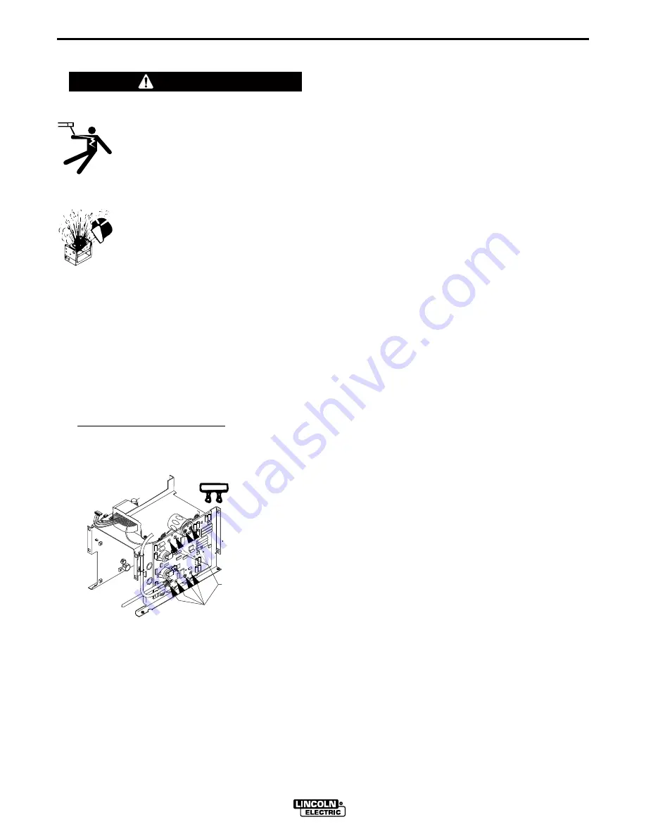
CAPACITOR DISCHARGE PROCEDURE
1. Obtain a power resistor (25 ohms, 25 watts).
2. Hold resistor body with electrically insulated glove.
DO NOT TOUCH TERMINALS. Connect the resis-
tor terminals across the two studs in the position
shown. Hold in each position for 1 second. Repeat
for all four capacitors.
3. Use a DC voltmeter to check that voltage is not
present across the terminals on all four capacitors.
CAPACITOR
TERMINALS
RESISTOR
Summary of Contents for INVERTEC V350-PRO CE
Page 34: ...NOTES ...


