


TIG MODULE
–
25
–
OPERATION
AMPTROL POSITION HAS
NO EFFECT ON THE
OUTPUT CURRENT.
LIGHT PRESSURE -
LOW OUTPUT CURRENT
HEAVY PRESSURE -
LOCAL
REMOTE
1
2
3
4
5
6
7
8
9
10
0
1
2
3
4
5
6
7
8
9
10
OUTPUT
HIGH
MED
LOW
45
90
120
160
200
250
RANGE
RANGE SETTING.
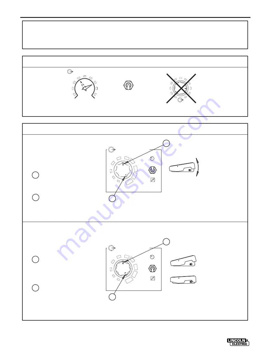
OUTPUT CONTROL
AT WELDER
OUTPUT CONTROL
REMOTE
CHOOSE REMOTE
OUTPUT CONTROL.
TIG MODULE SETTINGS
CURRENT CONTROL
A
USE OF THE CURRENT LIMIT CONTROL,
CHOOSE THE
NO EFFECT ON THE OUTPUT.
A
B
AVAILABLE BECAUSE THE CURRENT CONTROL
IS SET TO THE HALF-WAY POINT.
FULL OUTPUT IS AVAILABLE BECAUSE
CONTROL SETS THE MAXIMUM AVAILABLE
WELDING CURRENT.
THE CURRENT CAN BE VARIED FROM
MINIMUM TO HALF OF THE RANGER SETTING
BECAUSE THE CURRENT CONTROL IS SET TO
THE HALF-WAY POINT.
THE CURRENT CAN BE VARIED FROM
B
A
A
B
LOCAL
REMOTE
1
2
3
4
5
6
7
8
9
10
CURRENT CONTROL
A
A
B
MINIMUM TO MAXIMUM OF THE RANGER
SETTING BECAUSE THE CURRENT CONTROL
KNOB IS SET TO MAXIMUM.
REMOTE CURRENT CONTROL. THE CURRENT
HALF THE RANGER SETTING IS
ARC. THE CURRENT CONTROL SETS THE
WELDING CURRENT.
EXAMPLE 1:
OR AN AMPTROL IS USED TO START THE
AN ARC START SWITCH
AN AMPTROL IS USED FOR
EXAMPLE 2:
UP TO THE SETTING
OF THE CURRENT.
CONTROL.
THE CURRENT CONTROL IS SET TO MAXIMUM.
ARC START SWITCH, AND AMPTROL ON WELDERS
EQUIPPED WITH REMOTE CONTROL CAPABILITY.
WELDER SETTINGS
(IF APPROPRIATE)
THE OUTPUT DIAL HAS
FIGURE 9
Summary of Contents for TIG MODULE IM528-B
Page 21: ...NOTES 12b TIG MODULE...
Page 25: ...NOTES 14b TIG MODULE...
Page 50: ...NOTES...
Page 51: ...NOTES...