Page 12
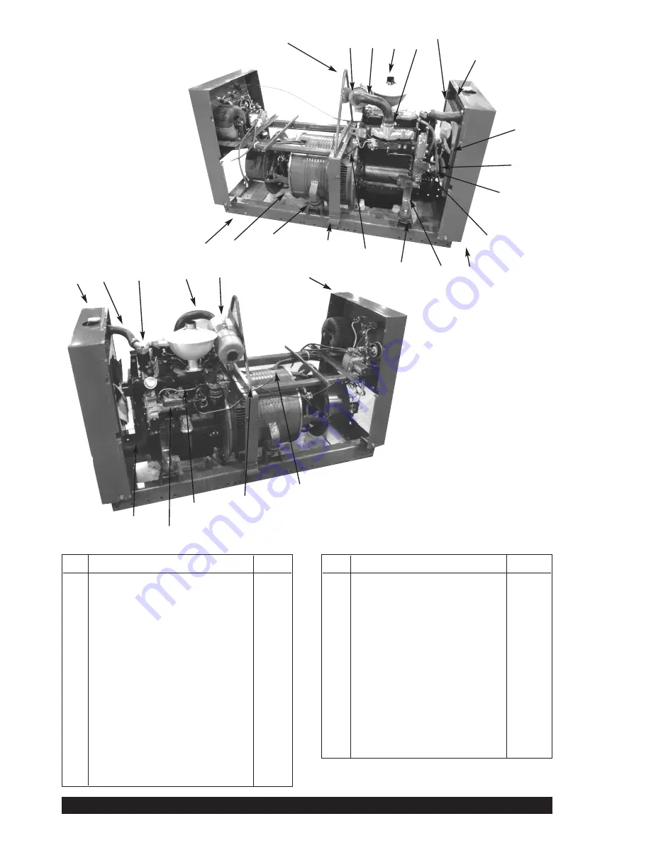
Shield-Arc 400AS-50
IMA 554C
1
68A
4
2
16,17
15, 17
21
29 A
48, 49, 50
97A
19, 20
66
3
109
95
13
103
100
14
104
26
97
67
63A
64
18A
18, 23, 24, 25,25A
5,6,9,10
11, 11A
5, 7, 8
9, 11A, 12
43, 44, 45
No.
Item
Part Name and Description
Req
1
Lift Bale Assembly
1
2
Rear End Frame Assembly
1
3
Front End Frame Assembly
1
4
Chassis Assembly
1
5
Hex. Head Bolt (
1
/
2
” UNC x3
1
/
4
”)
4
6
Washer
2
7
Rubber Mount - Engine
2
8
Rubber Mount - Engine (Top)
2
9
Nyloc Nut (
1
/
2
” UNC)
4
10
Rubber Mount - Generator
2
11
Rubber Mount - Generator (Top)
2
11A
Washer (
9
/
16
” I.D. x 3
3
/
8
” O.D).
12
12
Engine Mounting Spacer
4
13
Engine Foot
2
14
Engine Fan (Perkins Parts)
1
15
Bottom Radiator Hose
1
16
Top Radiator Hose
1
17
Radiator Hose Clamp
4
18
Radiator
1
18A
Radiator Shroud
1
19
Water Outlet
1
20
Flat Washer
2
Quote AP-33-C plus Machine Code No. and Serial No.
No.
Item
Part Name and Description
Req
21
Governor Adjust Pad Assembly
1
23
Hex. Head Screw (
5
/
16
” Whit. x
3
/
4
”)
4
24
Hex. Head Nut (
5
/
16
” Whit.)
4
25
Flat Washer (
5
/
16
” dia.)
4
25A
Lockwasher (
5
/
16
” dia.)
4
26
Rear Lower Panel Assembly
1
34
Transfer (Not Shown)
1
40
Battery (Not Shown)
1
41
Positive Lead (Not Shown)
1
42
Negative Lead (Not Shown)
1
43
Hex. Head Bolt (
1
/
2
” UNC x 1
1
/
4
”)
4
44
Lockwasher (
1
/
2
” dia.)
4
45
Hex. Nut (
1
/
2
” UNC)
4
48
Hex. Head Screw (
5
/
16
” Whit. x
3
/
4
”)
2
49
Hex. Nut (
5
/
16
” Whit.)
2
50
Lockwasher (
5
/
16
” dia.)
2
51
Hex. Head Screw (
5
/
16
” x
3
/
4
”)
4
52
Lockwasher (
5
/
16
” dia.)
4
53
Self Tapping Screw
16
BATTERIES UNDER RADIATOR
(NOT SHOWN)
AG-1236 4/2/87
GENERAL
ASSEMBLY
AP-33-C
Note:
In all Parts Lists, left and right
hand side should be determined
while standing facing the Generator
end of the Welder.
These illustrations show the 24 volt
unit which differs from the 12volt


