


A-5
INSTALLATION
SAE-400™
• USING A BOOSTER — connect positive lead
to battery first then connect negative lead
to negative battery lead at the lower control
panel support.
BATTERY ACID can burn eyes and skin.
•
Wear gloves and eye protection and be careful when
working near battery.
•
Follow instructions printed on battery.
IMPORTANT: To prevent ELECTRICAL DAMAGE WHEN:
a) Installing new batteries.
b) Using a booster.
Use correct polarity — Negative Ground.
To prevent BATTERY BUCKLING, tighten nuts on batteries only until
snug. DO NOT OVERTIGHTEN.
• Spark Arrester and Muffler may be hot!
• Allow engine to cool before servicing spark
arrester!
• Do not operate engine while servicing spark
arrester!
------------------------------------------------------------------
SPARK ARRESTER
Some federal, state or local laws may require that gasoline or
diesel engines be equipped with exhaust spark arresters when
they are operated in certain locations where unarrested sparks
may present a fire hazard. The muffler included with this welder
has been modified and now qualifies as a spark arrester. Spark
arresting mufflers will have a clean out service plug and will have
“USDA FS 5100-1c QUALIFIED SPARK ARRESTER” stamped on the
muffler shell. Any spark arrester must be serviced and properly
maintained.
An incorrect arrester may lead to damage to the engine or
adversely affect performance.
------------------------------------------------------------------
WELDING OUTPUT CABLES
With the engine off, connect the electrode and work cables to the
studs provided. These connections should be checked periodically
and tightened if necessary.
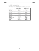
Listed in Table A.1 are copper cable sizes recommended for the
rated current and duty cycle. Lengths stipulated are the distance
from the welder to work and back to the welder again. Cable
sizes are increased for greater lengths primarily for the purpose of
minimizing cable voltage drop.
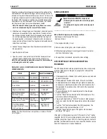
Table A.1 Combined Length of Electrode and Work Cables.
MACHINE GROUNDING
Because this portable engine driven welder creates its own power,
it is not necessary to connect its frame to an earth ground, unless
the machine is connected to premises wiring (home, shop, etc.).
To prevent dangerous electric shock, other equipment powered by
this engine driven welder must:
a) be grounded to the frame of the welder using a grounded
type plug, or
b) be double insulated.
When this welder is mounted on a truck or trailer, its frame must
be securely connected to the metal frame of the vehicle. When
this engine driven welder is connected to premises wiring such as
that in a home or shop, its frame must be connected to the system
earth ground. See the article on grounding in the latest U.S.
National Electrical Code and the local code.
In general, if the machine is to be grounded, it should be connect-
ed with a #8 or larger copper wire to a solid earth ground such as
a metal water pipe going into the ground for at least ten feet and
having no insulated joints, or to the metal framework of a building
which has been effectively grounded. The U.S. National Electrical
Code lists a number of alternate means of grounding electrical
equipment. A machine grounding stud marked with the
symbol is provided on the welding generator frame foot.
WARNING
CAUTION
Upto100FT.
Upto31m
2/0AWG
100-200FT.
31-61m
3/0AWG
200-250FT.
61-76m
4/0AWG
AMPS
@60%
DutyCycle
400
TOTALCOMBINEDLENGTHOFELEC-
TRODEANDWORKCABLES


