


IMA 599B
REDI-MIG 325
Page 11
e)
Burnback Control *
This control is located in the wire feed bay. The burnback
control adjusts the time period from when the drive motor
stops until the power source and gas solenoid are switched
off. [Approximately 0.1 seconds (when fully counterclock-
wise) to approximately 1.1 seconds (when fully clockwise)].
The purpose of the burnback control is to prevent the
electrode wire sticking in the weld crater at the finish of the
weld.
f)
Spot Welding *
In spot welding mode, welding takes place for a pre-set
time and then stops automatically. Welding time is
adjustable between 0.5 sec. and 4 sec. by operation of the
spot weld control on the front panel. There is a positive click
in the extreme anti-clockwise position to indicate that the
spot weld feature is “off”.
g)
Gas Purge/Wire Inch *
Use the gas purge momentry toggle switch to operate the
gas solenoid to purge air from the hose after connecting a
new gas cylinder. Gas purge will only operate while the
toggle switch is held upwards.
Use this same toggle switch to operate the wire feed motor
and “cold” inch the wire, by pushing the toggle switch
downwards.
h)
2 Step/4 Step Trigger Operation *
A two position toggle switch on the front panel provides two
modes of operation of the gun trigger. In 2 Step mode, the
gun trigger is pressed to start welding and released to stop.
In 4 Step mode, pressing the gun trigger only operates the
gas solenoid, allowing shielding gas to flow. Releasing the
trigger activates the contactor which starts the wire feed
motor and connects welding current to the wire so that
welding may commence. To stop welding, the trigger must
again be operated; pressing it stops the wire feed, activates
the burn back time delay and opens the contactor after the
pre-set burn back time. Releasing the trigger stops the gas
flow.
To recommence welding, the above cycle must be
repeated.
i)
Over temperature light
Indicates that the thermostats have operated to protect unit
from over temperature.
*
Mounted on REDI-MIG 4D wire feeder (Burnback is
mounted in the wire bay area).
The following items are required:
1)
A reel of wire of suitable size and type .
2)
A suitable gun and cable assembly with a “Euro” connector
and the correct tip and, if necessary gas nozzle for the
consumable being used. (A REDI-MIG 360 torch is supplied).
3)
Correct drive rolls for the wire size and type to be used. The
wire feeder is supplied with a 0.9/1.2mm solid wire feed roll
as standard; drive rolls for other types and sizes are
available as spare parts. (see table on page 12).
4)
A work return cable and clamp.(supplied)
5)
Normal welding accessories including helmet or hand
shield with suitable lens, gloves etc.
6)
If a gas shielded process is to be used, a cylinder of
appropriate gas is required. (Regulator/flowmeter and hose
are supplied.) If gas shielding is required, connect the gas
per Section 1.3 of this manual.
Remember that gas cylinders may explode if damaged, so ensure
that all gas cylinders are securely mounted.
Ensure that the correct type and size wire feed rolls are fitted. In
replacing wire feed rolls, ensure that the key and keyway are
correctly positioned and tighten the knurled locking screw
securely.
It is best to remove the gun before loading a new spool of wire.
Fit a spool of appropriate wire onto the 50mm spool hub so that,
as wire is fed, the spool turns clockwise. Carefully release the end
of the wire from the spool ensuring that the released end is held
to stop the wire from unravelling. Cut off the end kink to give a
smooth straight end of wire.
Obtain a gap between the wire feed roll and the pressure roll by
lifting the cam latch. Feed the wire end into the guide tube,
between the drive rolls, and into the “Euro” connector guide until
it protrudes about 20mm out of the front of the “Euro” connector.
Close the drive rolls by lowering the cam latch ensuring the rolls
firmly hold the wire. Ensure the wire is correctly aligned between
all four rolls and that the drive roll gear teeth mesh correctly
before lowering the cam latch. Poor alignment of wire or drive roll
gear teeth may cause wire slipping.
Refit the gun and cable assembly onto the “Euro” connector by
slipping the end of wire into the cable wire hole. Tighten the “Euro”
connector lock ring.
Activate the power source, set the wire feed speed to 4 on the dial
and press the Gas Purge/Wire Inch toggle switch downwards.
The wire feed roll should turn, feeding the wire further up the gun
and cable assembly. (Adjust the tension on the drive roll cam latch
so that the wire feeds smoothly. Do not overtighten).
Ensure there are no kinks or sharp bends in the gun cable and
hold the Gas Purge/Wire Inch toggle switch downwards until the
wire emerges from the gun. It is good practice to remove the tip
when first feeding a new coil of wire, then refitting the tip over the
wire and tightening.
Cut off the end of the wire leaving 10mm to 15mm stick-out from
the tip.
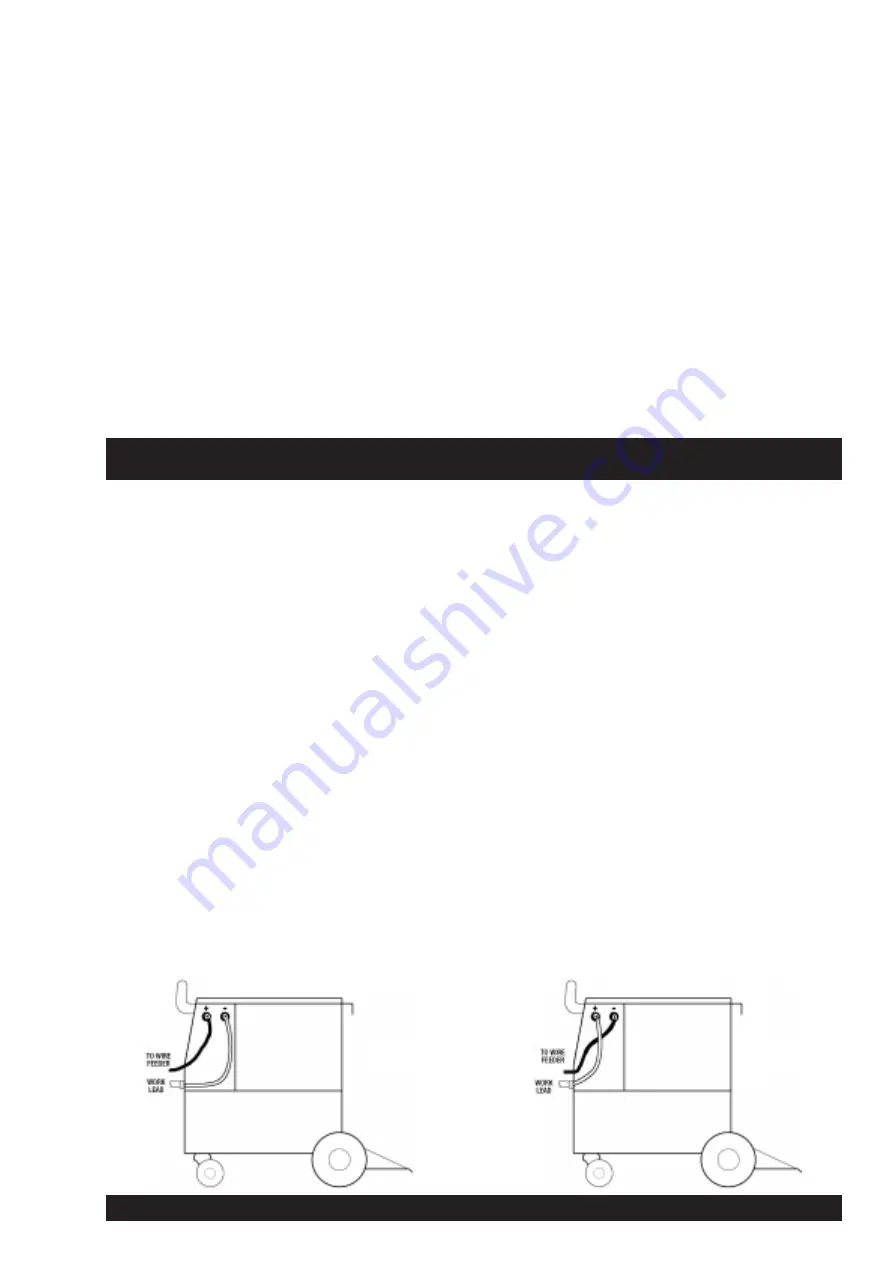
Select required polarity. See Section 1.5 - Output Polarity
Connection and diagrams below.
Section 3 - SETTING UP FOR WELDING
DC+
SETUP
DC-
SETUP
Gas Shielded Wires
Gasless Wires