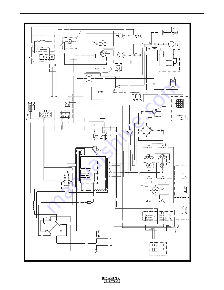
Lincoln Electric RANGER 300 D Operator'S Manual Download Page 48

F-8

WIRING DIAGRAM

F-8

RANGER 300 D AND 300 DLX

67

75A

3C

PCB2

BYPASS PC

4

1

76B

2

J10

227

76A

5E

4

BLACK

BLACK

11

RECEPTACLE

3B

125/250V. SINGLE

BLACK

BLACK

BLACK

BLACK

3F

3A

3B

201

B

1J10

2J10

222B

225

223

3J10

HIGH

GLOW PLUG

GLOW PLUGS

FLASHING CURRENT

5

AC

9

15A

50A

77B

201

CB2

75B

3

CB7

15A

J10

5

W4

254

TERMINALS

5L

GREEN

GND-C

5H

ENGINE GROUND

5H

PULL

HOLD

L3

FUEL

IG

L

ALTERNATOR

INDICATES JACK NUMBER

1J10

INDICATES CAVITY NUMBER

GREEN

75A

R3

MAX

10K POT

75

CW

76D

77

RHEOSTAT

RED

J3

214

200B

219

224

A1

R1

W12

R

ENGINE HARNESS CONNECTOR TO PANEL HARNESS   

GND

5E

15A

5K

222G

214

240

221

BOARD

PCB1

254B

254A

254

224D

222

213B

5F

214B

15A

77

BATTERY

214A

213A

227A

SWITCH

SHOWN IN

"HIGH"

POSITION

AUTO

235

224F

5F

250

222D

3G

GND-G

J8

120/240V

CB5

15A

3C

BLACK

12

76A

3A

77A

76B

75B

GND-B

5F

J11

J7

5D

75A

BLACK

  FUEL SHUTDOWN   SOLENOID (HARNESS LEAD END)

GROUND SCREW

 IDLER SOLENOID (HARNESS LEAD END)

ABOVE AMPHENOL HOLE

3H

GND-G

5A

WHITE

WHITE

WHITE

COLORED

TERM.

SILVER

WHITE

BLACK

BLACK

 ALTERNAT0R  CONNECTION  BLOCK (HARNESS LEAD END)

224A

222F

213

(+)

239

W15

W1

200A

OUTPUT

D2

ROTOR FIELD

(+)

(-)

BLACK

BLACK

CB6

5D

5L

J9

ELECTRODE

3E

J13

J12

227

224B

237

WORK

DC+

S1

SWITCH

75

76

5W

GAUGE

226

 SENDER

"SIG" TERMINAL

224E

+

240

222

224

CHARGER

SENSOR

254C

IDLER WELD

CURRENT

COIL

COIL

PULL

RED

L2

WHITE

-

BLACK

J11

R

TEMP.

WATER

220B

221C

12 VOLT

BATTERY

+

222E

220C

TEMP.

WATER

OIL

224E

224

S

CRANK

MOTOR

WHITE

COIL

COIL

SOLENOID

5E

67

21A

NOTES:

ELECTRICAL SYMBOLS PER E1537

ALL CASE FRONT COMPONENTS VIEWED FROM REAR.

GROUND

J12

FRAME

(-)

BLACK

J13

SHUTDOWN

220A

235B

CONTACTOR

237

5K

5K

REMOTE SWITCH

L1

(CHOKE)

W6

224G

R

224H

5G

221A

225

R

6J10

STARTER

SOLENOID

COIL

S5

SWITCH

IDLER

224B

222

RED

S4

S3

START

222G222G

SWITCH

223A

ON/OFF

S6

5B

PRESSURE

235A

222C

FUEL

8J10

FUEL 

9J10

235C

235B

BLUE

221B

CB9

(+)

222D

11J10

220

222B

BLUE

STARTER

ELECTRODE POLARITY

77B

REMOTE CONTROL

AC

DC-

AC

DC-

DC+

OUTPUT

D1

W11

RECTIFIER

R2

W16

50 W

25 OHM

77A

1

R3

3

SWITCH

C1

5

77D

S8

76

3D

3D

PC

CB8

15A

BLACK

BLACK

222E

222F

222J

222K

222H

HIGH

HOLD

SPEED

SOLENOID

5G

224F

ENGINE

HOUR METER

5H

SENSOR

CURRENT

IDLER AC

(-)

5

200B

7

201A

W7

5M

5M

W10

213

RED

BLACK

GND-D

200

RED

6

POSITIVE SLIP

RING NEAREST

LAMINATION

3

GND-E

BLACK

J5

201A

120 V

11

BLACK

R2

12J10

10

5

8

4

5A

2

J1

214

1

A2

REACTOR

C1

221

241

A1

W12

236

(-)

7J10

SWITCH

OIL PRESSURE

SWITCH

"ON" POSITION

10J10

SHOWN IN

SWITCH

222A

236

239

5J10

4J10

67

3

224A

12

11

10

9

8

5

1

24

219

(-)

RINGS

(+)

5A

BLOWER BAFFLE

C1

CB4

800 MFD

(SHOWN IN

REMOTE POSITION)

7

A

GND-E

STATOR

SILVER

COLORED

C

GROUND

 AMPHENOL

R6

R4

R7

R5

RANGE

S2

76A

W1

76D

77A

9
6

GROUND SCREW

3

WIRING DIAGRAM - RANGER 300 D

GND-C

CB3

50A

254A

W10

    L10556

   9-12-97A

77

6

3

TERMINALS

B

77A

76A

3

J6

F

W2

21A

GREEN

120 V

SILVER

COLORED

5B

(+)

SLIP

(+)

RED

AC

GND-D

6

3 TURNS

W7

W11

J2

250

1

6

220

200B

W4

4

201A

235

254B

A2

1

W9

3

NOTE:  This diagram is for reference only.   It may not be accurate for all machines covered by this manual.  The specific diag

ram for a particular code is pasted inside

the machine on one of the enclosure panels.  If the diagram is illegible, write to the Service Department for a replacement.  G

ive the equipment code number..

Summary of Contents for RANGER 300 D

Page 1: ...S EQUIPMENT WITHOUT READING THIS MANUAL AND THE SAFETY PRECAUTIONS CONTAINED THROUGHOUT And most importantly think before you act and be careful For use with machines having Code Numbers 10399 10400 10850 Sales and Service through Subsidiaries and Distributors Worldwide Cleveland Ohio 44117 1199 U S A TEL 216 481 8100 FAX 216 486 1751 WEB SITE www lincolnelectric com World s Leader in Welding and ...

Page 2: ...R WEARERS SHOULD CONSULT WITH THEIR DOCTOR BEFORE OPERATING Read and understand the following safety highlights For additional safety information it is strongly recommended that you purchase a copy of Safety in Welding Cutting ANSI Standard Z49 1 from the American Welding Society P O Box 351040 Miami Florida 33135 or CSA Standard W117 2 1974 A Free copy of Arc Welding Safety booklet E205 is availa...

Page 3: ...ical earth ground 3 f Maintain the electrode holder work clamp welding cable and welding machine in good safe operating condition Replace damaged insulation 3 g Never dip the electrode in water for cooling 3 h Never simultaneously touch electrically hot parts of electrode holders connected to two welders because voltage between the two can be the total of the open circuit voltage of both welders 3...

Page 4: ...event the welding sparks from starting a fire Remember that welding sparks and hot materials from welding can easily go through small cracks and openings to adjacent areas Avoid welding near hydraulic lines Have a fire extinguisher readily available 6 b Where compressed gases are to be used at the job site special precautions should be used to prevent hazardous situations Refer to Safety in Weldin...

Page 5: ...iv SAFETY iv ...

Page 6: ...he information must be followed to avoid minor personal injury or damage to this equipment CAUTION Please Examine Carton and Equipment For Damage Immediately When this equipment is shipped title passes to the purchaser upon receipt by the carrier Consequently Claims for material damaged in shipment must be made by the purchaser against the transportation company at the time the shipment is receive...

Page 7: ... Precautions B 2 Controls and Settings B 2 Welder Generator Controls B 3 Engine Controls B 4 Engine Operation B 5 Before Starting the Engine B 5 Starting the Engine B 6 Cold Weather Starting and Operation B 6 Stoping the Engine B 6 Break In Period B 7 Welding Operation B 7 AC DC Stick Constant Current Welding B 8 AC DC TIG Constant Current Welding B 9 DC Wire Feed Welding CV with Ranger 300 DLX B ...

Page 8: ...uel D 3 Bleeding The Fuel System D 3 Air Filter D 3 Tightening the Fan Belt D 3 Cooling System D 3 Battery Maintenance D 4 Welder Generator Maintenance D 5 Storage D 5 Cleaning D 5 Brush Removal and Replacement D 5 Troubleshooting Section E Safety Precautions E 1 How to Use Troubleshooting Guide E 1 Troubleshooting Guide E 2 thru E 4 Connection Diagrams Wiring Diagrams Dimension Print Section F Pa...

Page 9: ...33 lbs 300 DLX 949 4 mm 628 7 mm 1528 6 mm 480 8 kg 300 D 499 0 kg 300 DLX OUTPUT GENERATOR Welding Output Volts at Rated Amps Duty Cycle Max OCV 3700 RPM DC Constant Current 300 amps 25 volts 100 AC Constant Current 300 amps 25 volts 100 80 volts RMS DC Constant Voltage 300 D 200 amps 20 volts 100 DC Constant Voltage 300 DLX 300 amps 30 volts 60 DC Constant Voltage 300 DLX 280 amps 30 volts 100 A...

Page 10: ...erator s manual WARNING STORING 1 Store the machine in a cool dry place when it is not in use Protect it from dust and dirt Keep it where it can t be accidentally damaged from construction activities moving vehicles and other hazards 2 Drain the engine oil and refill with fresh 10W30 oil Run the engine for about five minutes to circulate oil to all the parts See the MAINTENANCE section of this man...

Page 11: ... attachment to the base of the welding equipment so there will be no undue stress to the framework 3 Proper placement of the equipment on the under carriage to insure stability side to side and front to back when being moved and when standing by itself while being operated or serviced WARNING 4 Typical conditions of use i e travel speed rough ness of surface on which the undercarriage will be oper...

Page 12: ...WARNING IMPORTANT To prevent ELECTRICAL DAMAGE WHEN a Installing new batteries b Using a booster Use correct polarity Negative Ground The RANGER 300 is shipped with the negative bat tery cable disconnected Before you operate the machine make sure the Engine Switch is in the OFF position and attach the disconnected cable securely to the negative battery terminal Remove the insulating cap from the n...

Page 13: ...t when you are welding at a distance from the welder Table A 1 lists recommended cable sizes and lengths for rated current and duty cycle Length refers to the distance from the welder to the work and back to the welder Cable diameters are increased for long cable lengths to reduce voltage drops Lincoln Electric offers a welding accessory kit with the properly specified welding cables See the ACCES...

Page 14: ... permanent ly installed as a standby power unit for 240 volt three wire single phase 50 ampere service Only a licensed certified trained electrician should install the machine to a premises or residential elec trical system Be certain that The installation complies with the National Electrical Code and all other applicable electrical codes The premises is isolated and no feedbacking into the utili...

Page 15: ... N NEUTRAL BUS GROUND PREMISES DISCONNECT AND SERVICE OVERCURRENT PROTECTION GND N NOTE No 6 COPPER CONDUCTOR CABLE SEE NATIONAL ELECTRICAL CODE FOR ALTERNATE WIRE SIZE RECOMMENDATIONS 240 VOLT GROUNDED CONDUCTOR 50AMP 240 VOLT DOUBLE POLE CIRCUIT BREAKER DOUBLE POLE DOUBLE THROW SWITCH RATING TO BE THE SAME AS OR GREATER THAN PREMISES SERVICE OVERCURRENT PROTECTION 50 AMP 120 240 VOLT PLUG NEMA T...

Page 16: ... up to 250 amps on AC 100 duty cycle rating on all output ranges Remote control capability standard on all models Amphenol receptacle for easy connection of Lincoln remote control accessories FOR AUXILIARY POWER 12 000 watts of 120 240 volt 60Hz AC auxiliary power Power for tools lights electric pumps and for stand by emergency power Drive a 2 HP motor provided it is started under no load Two 15 a...

Page 17: ...g output for stick SMAW welding and for TIG welding and it offers constant voltage output for DC semiautomatic wire feed welding GENERATOR The RANGER 300 gives AC generator output for medium use demands LIMITATIONS The Ranger 300 is not recommended for any processes besides those that are normally per formed using stick welding SMAW TIG welding GTAW MIG GMAW welding and Innershield FCAW welding Th...

Page 18: ...idle When a wire feeder or TIG Module control cable is attached to either the 6 pin of 14 pin amphenol con nector and the Welding Terminals switch is in the WELDING TERMINALS REMOTELY CONTROLLED position the contactor is open in low idle and high idle until and the wire feeder trigger or Amptrol is closed This closes the 2 4 circuit When the gun trigger or Amptrol is released the contactor opens a...

Page 19: ...g for 10 14 seconds 3 START PUSH BUTTON When the push button is held the starter motor cranks over the engine release the Button once the engine starts NOTE If you press the START push button when the engine is running you may damage the ring gear or starter motor 4 ENGINE HOUR METER Records engine running time Use to determine when to perform required maintenance 5 BATTERY LIGHT Is off when batte...

Page 20: ...s operated at speeds above the maximum rated speed Read and understand all safety instructions included in the Kubota instruction manual that is shipped with your RANGER 300 BEFORE STARTING THE ENGINE Check the engine oil level See Figure D 1 for location of dipstick 1 Be sure the machine is on a level surface 2 Remove the engine oil dipstick and wipe it with a clean cloth Reinsert the dipstick an...

Page 21: ...AUTION Ambient Temperature Above 50 F 10 C 50 F 10 C to 23 F 5 C Below 23 F 5 C Pre Heat Time NOT REQUIRED Approximately 5 seconds Approximately 10 seconds CAUTION Never press the Glow Plug button continuously for more than 20 seconds 7 Release the GLOW PLUG button and press the START button to crank the engine Release when the engine starts 8 Check that the indicator lights are off If not imme di...

Page 22: ...E CONTROL dial on the output control panel to the set tings that are best for your selected welding process RANGER 300 D AND 300 DLX CAUTION Low Idle No Load 2000 RPM High Idle No Load 3700 RPM AC CC Weld Output 300 Amps 25 Volts DC CC Weld Output 300 Amps 25 Volts DC CV Weld Output 300 Amps 28 Volts Auxiliary Power 12 000 kVA 30 gallons hour 1 0 liters hour 60 gallons hour 2 2 liters hour 1 1 gal...

Page 23: ...set at 10 and the welding current is to low move the RANGE switch to the next high est setting 7 Set the POLARITY switch to the desired polarity CC blue setting 8 Set the OUTPUT control For stick welding always use a setting between 5 and 10 on the dial blue range 9 Strike an arc and begin welding The OUTPUT control can be adjusted while welding DO NOT change the RANGE switch setting while welding...

Page 24: ...an affect the ultimate results of this application Request Lincoln publi cation N 675 for additional information Recommended Outershield electrodes are 045 1 1 mm 052 1 3 mm and 1 16 1 6 mm Outershield 71 and 1 16 1 6 mm Outershield 70 Request Lincoln publication GS 200 for additional information For MIG welding the recommended electrodes are 030 0 8 mm 035 0 9 mm and 045 1 1 mm L 50 and L 56 You ...

Page 25: ... depending on the electrode 6 Set the OUTPUT control to a setting between 1 and 10 that gives the most stable arc for the appli cation 7 Strike an arc and begin welding the OUTPUT control can be adjusted while welding DO NOT change the RANGE switch setting while welding This can result in damage to the switch AFTER YOU FINISH WELDING 1 Stop the engine 2 Allow the work to cool completely 3 Remove t...

Page 26: ...ngine goes to high idle Press Amptrol Welding starts immediately Press gun trigger Ranger 300 DLX contactor closes Welding starts immediately and engine goes to high idle Press gun trigger LN 25 contactor closes Welding starts immediately and engine goes to high idle Press gun trigger Ranger 300 DLX contactor closes Welding starts immediately and engine goes to high idle Press gun trigger Ranger 3...

Page 27: ...ONTROL CABLE WIRE FEED CV LN 25 INTERNAL CONTACTOR WIRE FEED CV LN 7 K240 CONTACTOR KIT Touch electrode to work Welding starts immediately and engine goes to high idle Press Amptrol Welding starts immediately Press gun trigger LN 25 contactor closes Electrode touches work welding starts immediately and engine goes to high idle Press gun trigger K240 contactor closes Welding starts immediately NO Y...

Page 28: ...20 240 dual voltage receptacle a 1 0 HP that draws less than 15 Amps at 120 V can be plugged into one of the 120 V duplex receptacles SIMULTANEOUS WELDING AND POWER LOADS Auxiliary power ratings are with no welding load Simultaneous welding and power loads are permitted by the following table The permissible currents shown assume that current is being drawn from either the 120 volt or 240 volt sup...

Page 29: ...rounding type plugs or approved double insulated tools with two wire plugs RANGER 300 D AND 300 DLX GND 120 V 120 V 240 V Maximum Current Draw from 120V Duplex Receptacles No Welding EACH HALF OF EACH 120V DUPLEX TOTAL FROM ONE 120V DUPLEX TOTAL FROM BOTH 120V DUPLEXES 240 V LOAD FROM FULL KVA RECEPTACLE 0 20 AMPS 30 AMPS 40 AMPS 50 AMPS 15 AMPS 15 AMPS 15 AMPS 15 AMPS 0 30 AMPS 30 AMPS 30 AMPS 20...

Page 30: ... shielding gas con trol for AC and DC GTAW TIG welding applications It provides contactor control of constant current weld ing power sources having an internal contactor The TIG Module is supplied without accessories Arc Start switches Amptrols cables torches and mount ing brackets must be purchased separately K939 1 Docking Kit For mounting the K930 1 TIG Module on top of the Ranger 300 K936 1 Co...

Page 31: ...d wire feeder for use with the Ranger 300 D is the K449 LN 25 This portable unit provides CC CV for flux cored arc welding FCAW and metal inert gas welding MIG for remote control use either a K857 Remote Control Kit 25 ft or a K444 1 Remote Voltage Control Kit 25 ft which mounts inside the LN 25 RANGER 300 D AND 300 DLX ...

Page 32: ... to the nearest Lincoln Field Service Shop ELECTRIC SHOCK can kill Do not touch electrically live parts or electrode with skin or wet clothing Insulate yourself from work and ground Always wear dry insulating gloves ENGINE EXHAUST can kill Use in open well ventilated areas or vent exhaust outside MOVING PARTS can injure Do not operate with doors open or guards off Stop engine before servicing Keep...

Page 33: ...utes and stop engine Wait 5 minutes to allow the oil to come down to the oil pan and check oil level again FIGURE D 1 OIL COMPONENT LOCATIONS OIL FILTER Change the oil filter the first time after 50 hours of operation Then under normal operating conditions change the oil filter at every oil change Change the oil filter as follows 1 Drain the oil from the engine and allow the oil filter to drain 2 ...

Page 34: ...n out any accumulated dust 2 If dust is sticking to the element blow compressed air through the element from the inside out Turn the element as you apply air Air pressure should be under 99 psi 68 newton cm2 Replace the fil ter if there is carbon or oil on the element 3 Replace the element at least every 600 hours of operation and sooner under dusty conditions TIGHTENING THE FAN BELT If the fan be...

Page 35: ...foot BATTERY ACID can burn eyes and skin Wear gloves and eye protection and be careful when working near battery Follow instructions printed on battery To prevent ELECTRICAL DAMAGE when a Installing a battery b Using a booster Use correct polarity Negative Ground To prevent BATTERY DISCHARGE if you have an ignition switch turn it off when engine is not running CLEANING THE BATTERY Keep the battery...

Page 36: ...e battery charger manu facturer for proper charger settings and charging time WELDER GENERATOR MAINTENANCE STORAGE Store the RANGER 300 in clean dry protected areas CLEANING Blow out the generator and controls periodically with low pressure air do this at least once a week in par ticularly dirty areas OUTPUT RANGE SELECTOR AND POLARITY SWITCHES Switch contacts should not be greased To keep con tac...

Page 37: ...nder the column labeled PROBLEM SYMP TOMS This column describes possible symptoms that the machine may exhibit Find the listing that best describes the symptom that the machine is exhibiting Step 2 POSSIBLE CAUSE The second column labeled POSSIBLE CAUSE lists the obvious external possibilities that may contribute to the machine symptom Step 3 RECOMMENDED COURSE OF ACTION This column provides a cou...

Page 38: ...engine compartment is open Oil pressure and charging indicator lights will not be on when engine switch is ON and engine is not running if CB9 is tripped 1 High coolant temperature Indicator light lit 1 Faulty battery 2 Loose connections at battery or alternator 3 Loose fan belt 4 Faulty engine alternator 1 Contact your Local Lincoln Authorized Field Service Facility 1 Charge Battery 2 Inspect cle...

Page 39: ... connection to work 2 Welding Terminals switch is in wrong position 3 Faulty high speed solenoid or faulty PC board 1 Auxiliary power load is less than 100 watts 2 Faulty high speed solenoid or faulty PC board 1 Faulty high speed solenoid 1 Set switch to Auto 2 Remove all external loads 3 Contact your Local Lincoln Authorized Field Service Facility for technical troubleshooting assistance 1 Make s...

Page 40: ...cles 3 GFCI tripped 4 Faulty welding alternator or faulty PC board 1 Wire Feeder Power circuit breaker open 2 Faulty wiring in control cable 3 Faulty wire feeder 1 Place switch in Always On position when welding without welding terminal control cable Refer to Operation chapter for proper switch function 2 Contact your Local Lincoln Authorized Field Service Facility for technical troubleshooting as...

Page 41: ...n before servicing Disconnect NEGATIVE BATTERY LEAD Do not touch electrically live parts Keep guards in place ELECTRODE TO WORK S23732 2 RANGER 300 D RANGER 300 DLX LN 25 ACROSS THE ARC CONNECTION DIAGRAM RANGER 300 DLX ONLY N C IF REMOTE OUTPUT CONTROL IS USED PLACE LOCAL REMOTE SWITCH IN REMOTE POSITION N B USE POLARITY SWITCH TO SELECT DESIRED ELECTRODE POLARITY POSITION RANGE SWITCH TO A WIRE ...

Page 42: ...OL REMOTE POSITIION ELECTRODE CABLE TO WIRE FEED UNIT TO LN 25 INPUT K626 XX INPUT CABLE ASSEMBLY Do not operate with panels open Disconnect NEGATIVE BATTERY LEAD before servicing S23732 3 WARNING Do not operate with panels open Disconnect NEGATIVE BATTERY LEAD before servicing Do not touch electrically live parts ELECTRODE TO WORK S23732 4 CAUTION AN INCREASE IN THE THE AC AUXILIARY VOLTAGE IF TH...

Page 43: ...TCH TO SET FOR DESIRED ELECTRODE POLARITY POSITION THE RANGE SWITCH TO A WIRE WELDING CV POSITION N D IF OPTIONAL REMOTE OUTPUT CONTROL IS USED PLACE OUTPUT CONTROL SWITCH IN OUTPUT CONTROL REMOTE POSITIION Disconnect NEGATIVE BATTERY LEAD Do not touch electrically live parts 14 PIN AMPHENOL TO WORK ELECTRODE before servicing Do not operate with panels open TO WORK CAUTION THE ENGINE WELDER OPERAT...

Page 44: ...ECTION 76 POWER SOURCE FRAME CONNECTION 77 CONNECTS TO WORK TERMINAL OF POWER SOURCE 42 VAC 21 GND 32 K488 SG TO WORK CONTROL MODULE RECEPTACLE 14 PIN WIRE FEEDER RANGER 115V RECEPTACLE THE ENGINE WELDER OPERATING MANUAL K487 25 SPOOL GUN BE SURE THAT CONTROL MODULE MODE SLIDE SWITCH IS IN THE LINCOLN CONTACT CLOSURE POSITION BEFORE ATTEMPTING TO OPERATE CONTROL MODULE INCORRECT SWITCH POSITION CO...

Page 45: ...ls open Disconnect NEGATIVE BATTERY LEAD before servicing INPUT REGULATOR TO GAS FITTING Do not touch electrically live parts CYLINDER ARGON GAS TO WORK ELECTRODE OR 6 PIN AMPHENOL K814 ARC START SWITCH S23732 10 K870 FOOT AMPTROL OR K963 1 HAND AMPTROL CRM after 9 23 97 CAUTION AN INCREASE IN THE THE AC AUXILIARY VOLTAGE IF THIS VOLTAGE GOES OVER 140 VOLTS WIRE FEEDER CONTROL CIRCUITS MAY BE ANY ...

Page 46: ...T CONTROL IS USED ELECTRODE WORK POWER SOURCE APPLICATIONS SEE OPERATOR S MANUAL OF 500 VOLT AMPERES N D LEADS 21 AND GND DO NOT APPEAR ON LN 7 S WITH CODES BELOW 7026 N C PLUG INTO 115 VOLT AC RECEPTACLE ON WELDER CONTROL PANEL OR OTHER 115 VOLT AC SUPPLY RATED AT A MINIMUM N B 3 CONDUCTOR 16 POWER CORD PHYSICALLY SUITABLE FOR THE INSTALLATION AND PLUG RATED AT 115 VOLTS 15 AMPERES AC SWITCH ON T...

Page 47: ... 254A J2 6 10 5 200 201 C5 240 31 IDLER S6 ON OFF IDLER AC J12 237 224B W4 L10262 PCB1 7 3 R CHARGER 5F 220 6 20 97 W13 C2 SWITCH W1 C3 2C 232 77A W5 224C GROUND SCREW BLOWER BAFFLE W4 5E SLIP RINGS 220 221 E GROUND AMPHENOL 2 247 SOLENOID SPEED HIGH HOLD 76B 75B 4B J10 1J10 INDICATES CAVITY NUMBER 800 MFD GREEN RECEPTACLE SILVER 3C GND G 6 W7 50W 240 241 R W2 3 5A 76A CB1 42 213 W6 ELECTRODE POLA...

Page 48: ...537 ALL CASE FRONT COMPONENTS VIEWED FROM REAR GROUND J12 FRAME BLACK J13 SHUTDOWN 220A 235B CONTACTOR 237 5K 5K REMOTE SWITCH L1 CHOKE W6 224G R 224H 5G 221A 225 R 6J10 STARTER SOLENOID COIL S5 SWITCH IDLER 224B 222 RED S4 S3 START 222G 222G SWITCH 223A ON OFF S6 5B PRESSURE 235A 222C FUEL 8J10 FUEL 9J10 235C 235B BLUE 221B CB9 222D 11J10 220 222B BLUE STARTER ELECTRODE POLARITY 77B REMOTE CONTRO...

Page 49: ...TPU T R H EO STAT S8 CW 75 10K PO T 76 GN D E 76D GN D D 201A AC 7 R ED RED 200B 21 31A 32 4A C O N TAC TO R 2A C 21 H W O R K 77C 76C 75C 31B I 42 K G N D A G R O U N D START S4 223A 222 ON P O SITION 225 223 222B GL OW P LUG 222B 222A 225 STARTE R 224B 1J10 HO LD L3 FUE L 5H 227 ALTERNATO R 254 254A J2 6 10 5 200 201 C5 240 31 IDLER S6 ON OFF I D LER AC J12 237 224B W4 PC B1 7 3 R CHA RG ER 5F 2...

Page 50: ...NGER 300 D AND 300 DLX 30 50 6 20 97 13 00 33 81 60 18 13 85 18 48 6 75 34 86 20 25 12 36 60 50 17 37 18 00 11 98 6 26 M18399 L 18 00 31 00 46 08 C RADIATOR CAP CENTER OF GRAVITY 24 2 70 9 96 24 04 24 75 DIMENSION PRINT RANGER 300 ...

Page 51: ...NOTES RANGER 300 D AND 300 DLX ...

Page 52: ...NOTES RANGER 300 D AND 300 DLX ...

Page 53: ...16 383 2259 and ask for the Welding School Registrar Lincoln Welding School BASIC COURSE 700 00 5 weeks of fundamentals There is a 10 discount on all orders of 50 00 or more for shipment at one time to one location Orders of 50 or less before discount or orders outside of North America must be prepaid with charge check or money order in U S Funds Only Prices include shipment by 4thClass Book Rate ...

Page 54: ...electrically live parts or electrode with skin or wet clothing Insulate yourself from work and ground No toque las partes o los electrodos bajo carga con la piel o ropa moja da Aislese del trabajo y de la tierra Ne laissez ni la peau ni des vête ments mouillés entrer en contact avec des pièces sous tension Isolez vous du travail et de la terre Berühren Sie keine stromführenden Teile oder Elektrode...

Page 55: ...gute Be und Entlüftung des Arbeitsplatzes Mantenha seu rosto da fumaça Use ventilação e exhaustão para remover fumo da zona respiratória Turn power off before servicing Desconectar el cable de ali mentación de poder de la máquina antes de iniciar cualquier servicio Débranchez le courant avant l entre tien Strom vor Wartungsarbeiten abschalten Netzstrom völlig öff nen Maschine anhalten Não opere co...

Page 56: ...s and Service through Subsidiaries and Distributors Worldwide Cleveland Ohio 44117 1199 U S A TEL 216 481 8100 FAX 216 486 1751 WEB SITE www lincolnelectric com World s Leader in Welding and Cutting Products ...

Reviews: