Lincoln Electric RANGER 10,000 Service Manual Download Page 34

RANGER® 10,000 & RANGER® 10,000 PLUS

MAINTENANCE

D-6

D-6

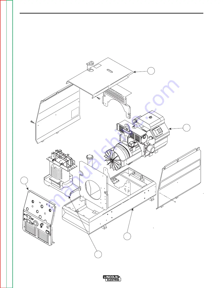
FIGURE D.1 - MAJOR COMPONENT LOCATION

44

11

33

55

22

1. CASEFRONT

2. OUTPUT RECTIFIER ASSEMBLY

3. BASE/UNDERCARRIAGE ASSEMBLY

4. ENGINE/ROTOR/STATOR ASSEMBLY

5. CASE TOP & SIDES

Retur

n

to

Section

TOC

Retur

n

to

Section

TOC

Retur

n

to

Section

TOC

Retur

n

to

Section

TOC

Retur

n

to

Master

TOC

Retur

n

to

Master

TOC

Retur

n

to

Master

TOC

Retur

n

to

Master

TOC

Summary of Contents for RANGER 10,000

Page 1: ...HROUGHOUT And most importantly think before you act and be careful SERVICE MANUAL For use with machine code numbers Kohler 11041 11151 11394 Honda 11095 11398 Robin Subaru 11253 11395 Sales and Service through Subsidiaries and Distributors Worldwide Cleveland Ohio 44117 1199 U S A TEL 216 481 8100 FAX 216 486 1751 WEB SITE www lincolnelectric com World s Leader in Welding and Cutting Products Copy...

Page 2: ...WITH THEIR DOCTOR BEFORE OPERATING Read and understand the following safety highlights For additional safety information it is strongly recommended that you purchase a copy of Safety in Welding Cutting ANSI Standard Z49 1 from the American Welding Society P O Box 351040 Miami Florida 33135 or CSA Standard W117 2 1974 A Free copy of Arc Welding Safety booklet E205 is available from the Lincoln Elec...

Page 3: ...ing open arc welding Headshield and filter lens should conform to ANSI Z87 I standards 4 b Use suitable clothing made from durable flame resistant material to protect your skin and that of your helpers from the arc rays 4 c Protect other nearby personnel with suitable non flammable screening and or warn them not to watch the arc nor expose themselves to the arc rays or to hot spatter or metal ELEC...

Page 4: ...void welding near hydraulic lines Have a fire extinguisher readily available 6 b Where compressed gases are to be used at the job site special precautions should be used to prevent hazardous situations Refer to Safety in Welding and Cutting ANSI Standard Z49 1 and the operating information for the equipment being used 6 c When not welding make certain no part of the electrode circuit is touching t...

Page 5: ... 4 Des gouttes de laitier en fusion sont émises de lʼarc de soudage Se protéger avec des vêtements de protection libres de lʼhuile tels que les gants en cuir chemise épaisse pan talons sans revers et chaussures montantes 5 Toujours porter des lunettes de sécurité dans la zone de soudage Utiliser des lunettes avec écrans lateraux dans les zones où lʼon pique le laitier 6 Eloigner les matériaux infl...

Page 6: ...S FOR ALL SECTIONS Safety i iv Installation Section A Operation Section B Accessories Section C Maintenance Section D Theory of Operation Section E Troubleshooting and Repair Section F Electrical Diagrams Section G Parts Manual P 481 Series RETURN TO MAIN INDEX ...

Page 7: ...utput Cables A 6 Angle of Operation A 6 High Altitude Operation A 6 Location Ventilation A 7 Connection of Wire Feeders A 7 Additional Safety Precautions A 7 Welder Operation A 7 Auxiliary Power A 8 120V Duplex Receptacles A 8 Motor Starting A 8 Electrical Devices used w RANGER 10 000 A 9 Auxiliary Power While Welding A 10 Stand by Power Connections A 10 Connection of RANGER 10 000 to Premises Wir...

Page 8: ...ooled Gasoline Engine Aluminum Alloy with Cast Iron Liners Electronic Ignition Operating Speed RPM High Idle 3700 Full Load 3500 Low Idle 2200 Displacement cu in cu cm 38 624 Kohler 37 5 614 Honda 39 9 653 ROBIN SUBARU Capacities Fuel 9 Gal 34 L Lubricating Oil 2 0 Qts 1 9 L Fuel 9 Gal 34 L Lubricating Oil 1 9 Qts 1 8L Fuel 12 Gal 45 4 L Lubricating Oil 1 6 Qts 1 6L Horsepower 20 HP 3600 RPM Kohle...

Page 9: ...5 Kohler CH23S K2468 2 Subaru Robin EH65 Description 2 cylinder 4 Cycle Air Cooled Gasoline Engine Aluminum Alloy with Cast Iron Liners Electronic Ignition Operating Speed RPM High Idle 3700 Full Load 3500 Low Idle 2200 Displacement cu in cu cm 41 674 Kohler 39 9 653 SUBARU ROBIN Capacities Fuel 9 Gal 34 L Lubricating Oil 2 0 Qts 1 9 L Fuel 9 Gal 34 L Lubricating Oil 1 6 Qts 1 6L Horsepower 23 HP ...

Page 10: ...asoline engines be equipped with exhaust spark arresters when they are operated in certain locations where unarrested sparks may present a fire hazard The standard muffler included with this welder does not qualify as a spark arrester When required by local reg ulations the K894 1 spark arrester must be installed and properly maintained An incorrect arrester may lead to damage to the engine or adv...

Page 11: ...surface on which the trailer will be operated environmental conditions 5 Conformance with federal state and local laws 1 1 Consult applicable federal state and local laws regarding specif ic requirements for use on public highways PRE OPERATION SERVICE READ the engine operating and maintenance instructions supplied with this machine CAUTION LUBRICATION SYSTEM CAPACITY INCLUDING FILTER Kohler CH20S...

Page 12: ...ru Robin Models For maximum rating de rate the welder output 3 5 for every 1000ft 305m above 3000ft 914m Honda Model For maximum rating de rate the welder output 3 5 for every 1000ft 305m above sea level If operation will consistently be at altitudes above 5 000 ft 1525m a carburetor jet designed for high altitudes should be installed This will result in better fuel economy cleaner exhaust and lon...

Page 13: ... DC or DC RANGER 10 000 and RANGER 10 000 PLUS Constant Current 225 Amps AC 25 Volts 210 Amps DC 25 Volts Constant Voltage 200 Amps DC 20 Volts d Position the RANGE switch to the WIRE FEED position e Attach the single lead from the LN 25 control box to the work using the spring clip on the end of the lead it carries no welding current f Place the engine switch in the AUTO position g Adjust wire fe...

Page 14: ...in ft m for Conductor Size Conductor size is based on maximum 2 0 voltage drop 14 AWG 12 AWG 10 AWG 8 AWG 6 AWG 4 AWG AUXILIARY POWER The RANGER 10 000 can provide up to 9 000 watts of 120 240 volts AC single phase 60Hz power for con tinuous use and up to 10 000 watts of 120 240 volts AC single phase 60Hz power peak use The RANGER 10 000 PLUS can provide up to 9 000 watts of 120 240 volts AC singl...

Page 15: ...rs These devices require large drills well pumps grinders small current inrush for starting refrigerators weed and hedge Some synchronous motors may trimmers be frequency sensitive to attain maximum output torque but they SHOULD BE SAFE from any frequency induced failures Capacitive Inductive Computers high resolution TV sets An inductive type line condition complicated electrical equipment er alo...

Page 16: ...bove 38 amperes will reduce output voltage below the allowable 10 of rated voltage which may damage appliances or other motor driven equipment 3 Install a 50 amp 120 240V plug NEMA type 14 50 to the Double Pole Circuit Breaker using a 4 con ductor cable that is properly sized for the ampacity and length to be used The 50amp 120 240V plug is available in the optional plug kit 4 Plug this cable into...

Page 17: ...SWITCH RATING TO BE THE SAME AS OR GREATER THAN PREMISES SERVICE OVERCURRENT PROTECTION 50 AMP 120 240 VOLT PLUG NEMA TYPE 14 50 50 AMP 120 240 VOLT RECEPTACLE Connection of RANGER 10 000 to premises wiring must be done by a licensed electrician and must comply with the National Electrical Code and all other applicable electrical codes Figure A 1 CONNECTION OF RANGER 10 000 OR RANGER 10 000 PLUS T...

Page 18: ... 000 RANGER 10 000 PLUS NOTES A 12 A 12 Return to Section TOC Return to Section TOC Return to Section TOC Return to Section TOC Return to Master TOC Return to Master TOC Return to Master TOC Return to Master TOC ...

Page 19: ... Welder Controls B 2 Engine Switch B 2 Range Switch B 3 Controls Dial B 3 Fuel Consumption B 3 Engine Operation B 4 Before Starting the Engine B 4 Starting the Engine B 4 Stopping the Engine B 4 Break in Period B 4 Welding Process Stick Tig B 5 Summary of Welding Processes B 6 Return to Master TOC Return to Master TOC Return to Master TOC Return to Master TOC ...

Page 20: ... is being drawn from the receptacles and not welding for 10 14 seconds the idler reduces the engine speed to low idle SAFETY PRECAUTIONS Do not attempt to use this equipment until you have thoroughly read the engine manufacturer s manual supplied with your welder It includes important safety precautions detailed engine starting operating and maintenance instructions and parts lists ELECTRIC SHOCK ...

Page 21: ...5 3 Liters Hour ROBIN SUBARU 20 5 H P P220 22 5 HP EH665 6 Gallons Hour 2 3 Liters Hour 8 Gallons Hour 3 0 Liters Hour 1 5 Gallons Hour 5 8 Liters Hour 1 6 Gallons Hour 6 1 Liters Hour 1 2 Gallons Hour 4 5 Liters Hour 1 6 Gallons Hour 6 1 Liters Hour HONDA 20 H P GX620KI 3 Gallons Hour 1 3 Liters Hour 7 Gallons Hour 2 8 Liters Hour 1 3 Gallons Hour 5 Liters Hour 1 5 Gallons Hour 5 9 Liters Hour 1 ...

Page 22: ...dle speed for a few minutes to cool the engine Stop the engine by placing the Engine switch in the OFF position A fuel shut off valve is not required on the RANGER 10 000 because the fuel tank is mounted below the engine BREAK IN PERIOD It is normal for any engine to use a greater amount of oil until the break in is accomplished Check the oil level twice a day during the break in period approxi ma...

Page 23: ...AMPS 120 TO 210 DC 225 AC AMPS The K930 TIG Module should be used with the RANGER 10 000 on high idle to maintain satisfactory operation It can be used in the AUTO position but the delay going to low idle after welding is ceased will be increased if the AFTER FLOW CONTROL is set above 10 seconds NOTE For AC TIG Welding the maximum TIG welding output currents on each range setting will be approxi m...

Page 24: ...diately and engine goes to high idle NOTE Output Control must be set above 3 TIG TIG MODULE WITH Yes High Cold Press Arc Start Switch WITH CONTACTOR KIT contactor closes CONTROL CABLE ARC welding starts immediately START SWITCH WIRE FEED LN 15 No High Cold Press gun trigger ACROSS the ARC LN 15 contactor closes has internal contactor Welding starts immediately Note Output Control must be set above...

Page 25: ...ion C 1 TABLE OF CONTENTS ACCESSORIES SECTION Accessories Section C Optional Equipment C 2 Recommended Equipment C 3 Stick C 3 Wirefeed C 3 TIG C 3 Plasma Cutting C 3 Return to Master TOC Return to Master TOC Return to Master TOC Return to Master TOC ...

Page 26: ... Kit provides four 120V plugs rated at 15 amps each and one dual voltage Full KVA plug rated at 120 240V 50 amps K802 N Power Plug Kit Provides four 120V plugs rated at 20 amps each and one dual voltage full KVA plug rated at 120 240V 50 amps K894 1 Spark Arrester Kit Includes a heavy gauge steel approved spark arrester and clamp for easy mounting to muffler exhaust pipe K1690 1 GFCI RECEPTACLE KI...

Page 27: ...m Gun Connector Kit are required for gas shielded welding Innershield Gun is required for gasless welding K126 2 Magnum 350 Innershield Gun for LN 25 LN 15 K1802 1 Magnum 300 MIG Gun for LN 25 includes Connector Kit K470 2 Magnum 300 MIG Gun for LN 15 requires K466 10 Magnum Gun Connector Kit K1500 1 Gun Receiver Bushing for LN 15 K126 2 Note See Wire Feeder IM Manual for appropriate Drive Roll Gu...

Page 28: ...0 000 RANGER 10 000 PLUS NOTES C 4 C 4 Return to Section TOC Return to Section TOC Return to Section TOC Return to Section TOC Return to Master TOC Return to Master TOC Return to Master TOC Return to Master TOC ...

Page 29: ...ety Precautions D 2 Routine Maintenance D 2 Change the Oil D 2 Engine Oil Refill Capacities D 2 Change the Oil Filter D 3 Engine Adjustments D 4 Slip Rings D 4 Hardware Battery D 4 Engine Maintenance Parts D 5 Major Component Location D 6 Return to Master TOC Return to Master TOC Return to Master TOC Return to Master TOC ...

Page 30: ...d oil fil ter are not changed according to the manufac turerʼs recommendation ENGINE OIL CHANGE Drain the oil while the engine is warm to assure rapid and complete draining Remove the oil filler cap and dipstick Remove the yellow cap from the oil drain valve and attach the flex ible drain tube supplied with the machine Push in and twist the drain valve counterclockwise Pull the valve out and drain...

Page 31: ...n 5 Refill the crankcase with the specified amount of the recommended oil Reinstall the oil filler cap 6 Start the engine and check for oil filter leaks 7 Stop the engine and check the oil level If necessary add oil to the upper limit mark on the dipstick AIR CLEANER AND OTHER MAINTENANCE Air Cleaner With normal operating conditions the maintenance schedule for cleaning and re oiling the foam pre ...

Page 32: ...over 2 If the battery requires charging from an external charger disconnect the negative battery cable first and then the positive battery cable before attaching the charger leads Failure to do so can result in damage to the internal charger components When reconnecting the cables connect the positive cable first and the negative cable last GASES FROM BATTERY can explode Keep sparks flame and ciga...

Page 33: ...en using this filter ENGINE MAINTENANCE PARTS KOHLER C23S SUBARU ROBIN EH65 KOHLER 1205001 SUBARU ROBIN Oil Filter FRAM PH8172 248 65801 00 FRAM PH4967 Air Filter KOHLER 4708303 SUBARU ROBIN Element FRAM CA79 263 32610 A1 Air Filter KOHLER 2408302 N A Pre Cleaner Fuel Filter KOHLER 2405010 SUBARU ROBIN 011 00600 20 Spark Plugs CHAMPION RC12YC SUBARU ROBIN Resistor 030 GAP X65 01407 30 Type NGK BPR...

Page 34: ... 3 5 5 2 2 1 CASEFRONT 2 OUTPUT RECTIFIER ASSEMBLY 3 BASE UNDERCARRIAGE ASSEMBLY 4 ENGINE ROTOR STATOR ASSEMBLY 5 CASE TOP SIDES Return to Section TOC Return to Section TOC Return to Section TOC Return to Section TOC Return to Master TOC Return to Master TOC Return to Master TOC Return to Master TOC ...

Page 35: ...L ALTERNATOR CV TAP PRINTED CIRCUIT BOARD FIGURE E 1 RANGER 10 000 BLOCK LOGIC DIAGRAM Section E 1 Section E 1 Theory of Operation Section E Battery Starter Engine Excitation Rotor Stator and Idler Solenoid E 2 Rotor Field Feedback and Auxiliary Power E 3 Weld Winding Reactor and Range Switch E 4 Output Bridge Choke Polarity Switch and Output Terminals E 5 TABLE OF CONTENTS THEORY OF OPERATION SEC...

Page 36: ...nt of current in the rotor winding The flywheel alternator located on the engine supplies charging current for the battery circuit The battery circuit provides power for the printed circuit board and also for the idler solenoid The idler solenoid is mechanically connected to the engine throttle linkage If no current is being drawn from the RANGER 10 000 the printed circuit board activates the idle...

Page 37: ...rotor and the engine is running at high speed 3700 RPM a 230 AC voltage is developed in the stator auxiliary winding This winding is tapped to provide 115 VAC The two voltages 115 VAC and 230 VAC are connected to the appropriate receptacles and offer 9000 watts total of continuous AC power FIGURE E 3 ROTOR FIELD FEEDBACK AND AUXILIARY POWER STARTER ENGINE BATTERY IDLER SOLENOID OUTPUT CONTROL MECH...

Page 38: ...r the welding current If a constant voltage is desired for wire feeding then the reactor is bypassed and the range switch is con nected to a tap on the stator weld winding to provide a lower but stiffer output voltage STARTER ENGINE BATTERY IDLER SOLENOID OUTPUT CONTROL MECHANICAL ROTATION FIELD CAPACITOR ROTOR SLIP RINGS 115 230VAC RECEPT ACLES ROTOR STATOR STATOR REACTOR RANGE SWITCH OUTPUT BRID...

Page 39: ...he current path is through the Output Bridge where the AC voltage is rectified to a DC voltage and then to the choke where the DC output is filtered The filtered DC current path is through the Polarity Switch and on to the Output Terminals STARTER ENGINE BATTERY IDLER SOLENOID OUTPUT CONTROL MECHANICAL ROTATION FIELD CAPACITOR ROTOR SLIP RINGS 115 230VAC RECEPT ACLES ROTOR STATOR STATOR REACTOR RA...

Page 40: ...0 000 RANGER 10 000 PLUS NOTES E 6 E 6 Return to Section TOC Return to Section TOC Return to Section TOC Return to Section TOC Return to Master TOC Return to Master TOC Return to Master TOC Return to Master TOC ...

Page 41: ...tput Waveform CV Mode Machine Loaded F 34 Typical DC Weld Output Waveform CC Mode Machine Loaded F 35 Typical AC Weld Output Waveform Machine Loaded F 36 Abnormal Open Circuit Weld Voltage Waveform CV Mode one diode open F 37 Abnormal Open Circuit DC Weld Voltage Waveform F 38 Normal Open Circuit Weld Voltage Waveform CV Mode F 39 Normal Open Circuit DC Weld Voltage Waveform F 40 Normal Open Circu...

Page 42: ...al these tests can be con ducted without removing the case wrap around cover Step 3 PERFORM COMPONENT TESTS The last column labeled Recommended Course of Action lists the most likely components that may have failed in your machine It also specifies the appropriate test procedure to verify that the sub ject component is either good or bad If there are a number of possible components check the compo...

Page 43: ...r near paper plastic or cloth which could have a static charge If the PC board canʼt be installed immediately put it back in the static shield ing bag If the PC board uses protective shorting jumpers donʼt remove them until installation is complete If you return a PC board to The Lincoln Electric Company for credit it must be in the static shielding bag This will prevent further damage and allow p...

Page 44: ...ad 216 to frame ground This is the flashing voltage and is present only when the Start Run Stop switch S3 is in the Start position If the 12 VDC is missing check the leads switches and connections associated with the lead 216 See Wiring Diagram Check for the presence of 12 VDC at the pc board from lead 224 to frame ground This is the supply voltage to the board and is present when the engine is ru...

Page 45: ...es clamps and electrode holder for loose or broken connections 1 Disconnect lead W1 from the Output Bridge D1 and check for the presence of 80VAC from lead W1 to lead W2 on the main stator winding See wiring dia gram If the AC voltage is NOT present the winding in the sta tor may be faulty Check the winding for continuity and test to be sure it is NOT grounded to the stator iron Replace if nec ess...

Page 46: ...elding output is normal Engine runs normally 1 If machine is equipped with cir cuit breakers check circuit breakers CB1 thru CB5 Reset if tripped 2 Make sure the Output Control R1 is set at the maximum position 3 Check for loose or faulty plug s at the power receptacle s 1 Check the auxiliary power receptacles and associated wires for loose or faulty connec tions 2 Perform the Auxiliary and Field ...

Page 47: ...horized Service Facility 2 The engine RPM may be low 1 If the engine HIGH IDLE RPM is low then perform The Throttle Adjustment Test 2 Perform the Rotor Voltage Test 3 If the rotor voltage is low the Field Capacitor C1 or the Field Bridge D2 may be faulty Test and replace if necessary 4 Check the Output Control Potentiometer Normal resis tance is 10 000 ohms Also check associated wiring for loose o...

Page 48: ...ocess being used 1 Perform the Output Bridge Test 2 Check the Choke L1 the Polarity Switch S2 and associ ated wires for loose or faulty connections Check the choke winding for continuity and test to be sure it is NOT grounded the choke iron No AC welding output DC welding output and auxiliary power is nor mal 1 Make sure the Polarity Switch is in the proper position and is seated correctly 2 Make ...

Page 49: ... COURSE OF ACTION OUTPUT PROBLEMS No constant voltage CV welding output Constant current CC and the auxiliary power are operating normally 1 Make sure the Range Switch S1 is in the proper position CV and seated correctly 2 Make sure the wire feeder is connected correctly 1 Check the operation of the Range Switch S1 and check the associated wires for loose or faulty connections See Wiring Diagram 2...

Page 50: ...cles 1 With the Idler Switch S4 in the Auto position check for the presence of 12VDC at leads 213 to 215 located at the Idler Solenoid If 12VDC is pre sent and the Idler Solenoid is not activating then the solenoid may be faulty or there is a mechanical restriction prevent ing it from functioning 2 If there is NOT 12VDC at leads 213 to 215 then test for 12VDC from lead 213 to ground lead 5 See Wir...

Page 51: ...ctions are tight at the Electrode Output Terminal and also at the Polarity Switch See Wiring Diagram 2 Make sure the leads are looped three times through the current sensor on the Printed Circuit Board Engine will not go to high idle when attempting to weld or when the auxiliary power is loaded Welding output and auxiliary power output is normal when Idler Switch is in the HIGH position 1 Make sur...

Page 52: ...ne shuts off 1 The Engine may be low on or out of fuel 2 The Oil level may be low Check and fill to proper level 3 The fuel filter may be clogged 1 The oil pressure switch may be faulty Replace if necessary 2 The fuel shut off solenoid may be faulty Kohler Engines only Engine does not develop full power 1 The fuel filter may be clogged Replace if necessary 2 The air filter may be clogged Replace i...

Page 53: ... Max If the correct voltage is present at the output terminals then check for loose connections on the heavy cur rent carrying leads inside the RANGER 8 See Wiring Diagram 2 If the OCV is low at the welder output terminals then Perform The Engine Throttle Adjustment Test 3 Perform the Output Rectifier Bridge Test 4 Check for shorted or grounded windings in the reactor and also in the main stator S...

Page 54: ... 000 RANGER 10 000 PLUS NOTES F 14 F 14 Return to Section TOC Return to Section TOC Return to Section TOC Return to Section TOC Return to Master TOC Return to Master TOC Return to Master TOC Return to Master TOC ...

Page 55: ...nderstand the test procedures or are unable to perform the test repairs safely contact the Lincoln Electric Service Department for electrical trou bleshooting assistance before you proceed Call 1 888 935 3877 TEST DESCRIPTION This test will determine if the correct DC voltage is being applied to the rotor at maximum engine speed 3700 RPM This information will aid the technician in determining if t...

Page 56: ...ct the negative meter probe to the other brush lead 219 10 Start the engine and run it at high idle 3650 RPM Set the output control to the MAXIMUM position position 10 11 Check the voltage reading on the volt meter It should read between 37 and 46 VDC 12 If the voltage reading is low or not pre sent the generator field is not functioning properly Perform the Rotor Resistance Test The Field Diode B...

Page 57: ...etailed throughout this manu al If for any reason you do not understand the test procedures or are unable to perform the test repairs safely contact the Lincoln Electric Service Department for electrical trou bleshooting assistance before you proceed Call 1 888 935 3877 TEST DESCRIPTION This test will determine if there is a shorted winding in the rotor or if the rotor is grounded MATERIALS NEEDED...

Page 58: ...ct the test with the gasoline engine OFF 8 Remove the spark plug wires to prevent accidental engine kickback or starting 9 Isolate the rotor electrically by removing the generator brush leads Refer to Figure F 2 as you perform the remaining steps 10 Remove lead 219 from the negative brush 11 Remove lead 200A from the positive brush 12 Measure the resistance across the rotor slip rings A Set the oh...

Page 59: ... If the test does not meet the resistance specifications then the rotor may be faulty Replace the rotor If the test does meet the resistance specifications then the rotor is okay 14 Connect lead 200A to the positive brush which is the one nearest the rotor lamination Connect lead 219 to the negative brush 15 Reinstall the case side case top fuel cap lift bail gasket and spark plug wires Return to ...

Page 60: ... 000 RANGER 10 000 PLUS NOTES F 20 F 20 Return to Section TOC Return to Section TOC Return to Section TOC Return to Section TOC Return to Master TOC Return to Master TOC Return to Master TOC Return to Master TOC ...

Page 61: ...understand the test procedures or are unable to perform the test repairs safely contact the Lincoln Electric Service Department for electrical trou bleshooting assistance before you proceed Call 1 888 935 3877 TEST DESCRIPTION This test will determine if the correct AC voltages are being generated from the stator windings MATERIALS NEEDED Volt Ohmmeter 5 16 Nut driver Wiring Diagram RANGER 10 000 ...

Page 62: ... the fuel cap and lift bail rubber gasket With the 5 16 nut driver remove the case top and left side then reinstall the fuel cap 2 Connect the volt ohmmeter probes to leads 6 and 3 where they connect to the 230 VAC receptacle NOTE It is easier to insert the probes direct ly into the receptacle to perform this test However the probes may not reach in far enough to make or keep a good connection In ...

Page 63: ...ge reading It should be between 36 and 43 VAC If any one or more of the readings are missing or not within specifications then check for loose or broken wires between the test points and the stator windings See the Wiring Diagram Make sure the windings are NOT grounded internally to the stator iron If the leads are intact then the stator may be faulty Replace the stator If the voltage readings are...

Page 64: ... 000 RANGER 10 000 PLUS NOTES F 24 F 24 Return to Section TOC Return to Section TOC Return to Section TOC Return to Section TOC Return to Master TOC Return to Master TOC Return to Master TOC Return to Master TOC ...

Page 65: ...roughout this manual If for any reason you do not understand the test procedures or are unable to perform the test repairs safely contact the Lincoln Electric Service Department for electrical trou bleshooting assistance before you proceed Call 1 888 935 3877 TEST DESCRIPTION This test will determine if there are faulty diodes in the Output Rectifier Bridge MATERIALS NEEDED Volt Ohmmeter 5 16 Nut ...

Page 66: ... and 6 extension remove the nuts and washers holding the diode bridge pigtails and the heavy current carrying leads to the studs located in the middle of the rec tifier assembly Note their locations and the order of fasteners for reassembly 11 Electrically isolate the diode connectors by slightly bending them back into free air 12 With an ohmmeter or diode tester check each of the four diodes from...

Page 67: ...e test procedures or are unable to perform the test repairs safely contact the Lincoln Electric Service Department for electrical trou bleshooting assistance before you proceed Call 1 888 935 3877 TEST DESCRIPTION This test will determine if the Flywheel Alternator Regulator and associated circuitry are functioning properly MATERIALS NEEDED Volt Ohmmeter 5 16 Nut driver Wiring Diagram WARNING RANG...

Page 68: ... local engine repair facility 4 If the voltage reading is correct then check the output of the voltage regulator to deter mine the charging voltage for the battery Run the engine at high idle 3650 RPM Set the voltmeter for DC volts and place one meter probe on the middle lead and one probe on the green ground wire con nected to the voltage regulator See Figure F 5 for location Check for 13 15 VDC ...

Page 69: ... Service Department for electrical trou bleshooting assistance before you proceed Call 1 888 935 3877 TEST DESCRIPTION If the machine output is low this test will determine whether the gasoline engine is operating at the correct speed RPM during both HIGH and LOW idle conditions Directions for adjust ing the throttle to the correct RPM are given MATERIALS NEEDED 5 16 Nut driver 3 8 open end or box...

Page 70: ...re with the gasoline engine OFF 6 Remove the spark plug wires to prevent accidental engine kickback or starting 7 With the black or red marking pencil place a mark on one of the blower paddles See Figure F 6 for location 8 Connect the strobe tach according the manufacturer s instructions 9 Reconnect the spark plug wires and start the engine Direct the strobe tach light on the blower paddle and syn...

Page 71: ...acles 2 Start the engine and check the frequency counter At HIGH IDLE 3700 RPM the counter should read 60 8 to 62 5 Hz At LOW IDLE 2200 RPM the counter should read 35 8 to 37 5 Hz Note that these are median measurements hertz readings may vary slightly above or below 3 If either of the readings is incorrect adjust the throttle as follows Adjust HIGH IDLE Use the 3 8 wrench to turn the spring loade...

Page 72: ...the engine as possible With the machine case top removed the top of the air cleaner is the best location 2 Start the engine and observe the whip handle of the vibratach At HIGH IDLE 3700 RPM the whip handle should exhibit maximum oscillation At LOW IDLE 2200 RPM the whip handle should exhibit minimum oscillation Note that these are median measurements vibrat ach readings may vary slightly above or...

Page 73: ...ting machine Note that each vertical division represents 50 volts and that each horizontal division represents 5 milliseconds in time Note Scope probes connected at machine 115 VAC receptacle NORMAL OPEN CIRCUIT VOLTAGE WAVEFORM 115 VAC SUPPLY HIGH IDLE NO LOAD OUTPUT CONTROL AT MAXIMUM Return to Section TOC Return to Section TOC Return to Section TOC Return to Section TOC Return to Master TOC Ret...

Page 74: ... vertical division represents 20 volts and that each horizontal division represents 5 milliseconds in time The machine was loaded with a resistance grid bank Note Scope probes connected at machine output terminals TYPICAL DC WELD OUTPUT WAVEFORM CV MODE MACHINE LOADED MACHINE LOADED TO 200 AMPS AT 20 VDC Return to Section TOC Return to Section TOC Return to Section TOC Return to Section TOC Return...

Page 75: ...hine was loaded with a resistance grid bank Note Scope probes connected at machine output terminals SCOPE SETTINGS Volts Div 20V Div Horizontal Sweep 5 ms Div Coupling DC Trigger Internal MACHINE LOADED TO 200 AMPS AT 26 VDC TYPICAL DC WELD OUTPUT WAVEFORM CC MODE MACHINE LOADED CH1 0 volts 5 ms 20 volts Return to Section TOC Return to Section TOC Return to Section TOC Return to Section TOC Return...

Page 76: ... machine was loaded with a resistance grid bank Note Scope probes connected at machine output terminals SCOPE SETTINGS Volts Div 20V Div Horizontal Sweep 5 ms Div Coupling DC Trigger Internal MACHINE LOADED TO 225 AMPS AT 25 VDC TYPICAL AC WELD OUTPUT WAVEFORM MACHINE LOADED CH1 0 volts 5 ms 20 volts Return to Section TOC Return to Section TOC Return to Section TOC Return to Section TOC Return to ...

Page 77: ...rizontal division repre sents 5 milliseconds in time Note Scope probes connected at machine output terminals SCOPE SETTINGS Volts Div 20V Div Horizontal Sweep 5 ms Div Coupling DC Trigger Internal ABNORMAL OPEN CIRCUIT WELD VOLTAGE WAVEFORM CV MODE HIGH IDLE NO LOAD OUTPUT CONTROL AT MAXIMUM ONE OUTPUT DIODE NOT FUNCTIONING CH1 0 volts 5 ms 20 volts Return to Section TOC Return to Section TOC Retu...

Page 78: ...horizontal division repre sents 5 milliseconds in time Note Scope probes connected at machine output terminals SCOPE SETTINGS Volts Div 50V Div Horizontal Sweep 5 ms Div Coupling DC Trigger Internal ABNORMAL OPEN CIRCUIT DC WELD VOLTAGE WAVEFORM HIGH IDLE NO LOAD OUTPUT CONTROL AT MAXIMUM ONE OUTPUT DIODE NOT FUNCTIONING CH1 0 volts 5 ms 50 volts Return to Section TOC Return to Section TOC Return ...

Page 79: ...liseconds in time Note Scope probes connected at machine output terminals SCOPE SETTINGS Volts Div 20V Div Horizontal Sweep 5 ms Div Coupling DC Trigger Internal NORMAL OPEN CIRCUIT WELD VOLTAGE WAVEFORM CV MODE HIGH IDLE NO LOAD OUTPUT CONTROL AT MAXIMUM CH1 0 volts 5 ms 20 volts Return to Section TOC Return to Section TOC Return to Section TOC Return to Section TOC Return to Master TOC Return to...

Page 80: ...seconds in time Note Scope probes connected at machine output terminals SCOPE SETTINGS Volts Div 50V Div Horizontal Sweep 5 ms Div Coupling DC Trigger Internal NORMAL OPEN CIRCUIT DC WELD VOLTAGE WAVEFORM CC MODE HIGH IDLE NO LOAD OUTPUT CONTROL AT MAXIMUM CH1 0 volts 5 ms 50 volts Return to Section TOC Return to Section TOC Return to Section TOC Return to Section TOC Return to Master TOC Return t...

Page 81: ...illiseconds in time Note Scope probes connected at machine output terminals SCOPE SETTINGS Volts Div 50V Div Horizontal Sweep 5 ms Div Coupling DC Trigger Internal NORMAL OPEN CIRCUIT AC WELD VOLTAGE WAVEFORM HIGH IDLE NO LOAD OUTPUT CONTROL AT MAXIMUM CH1 0 volts 5 ms 50 volts Return to Section TOC Return to Section TOC Return to Section TOC Return to Section TOC Return to Master TOC Return to Ma...

Page 82: ... 000 RANGER 10 000 PLUS NOTES F 42 F 42 Return to Section TOC Return to Section TOC Return to Section TOC Return to Section TOC Return to Master TOC Return to Master TOC Return to Master TOC Return to Master TOC ...

Page 83: ...ut this manual If for any reason you do not understand the test procedures or are unable to perform the test repairs safely contact the Lincoln Electric Service Department for electrical trou bleshooting assistance before you proceed Call 1 888 935 3877 DESCRIPTION The following procedure will aid the technician in accessing the generator brushes for maintenance or replacement MATERIALS NEEDED 5 1...

Page 84: ...clip is beveled so that the brush can go in only one way 13 Snap the plastic retainer back onto the brush holder The brushes may need some repositioning wiggle them slightly to help them seat properly on the slip rings 14 To reinstall the brushes depress the spring loaded brushes into the holder and slip a suitable non metallic fairly stiff retainer through the slots at the top and bottom of the h...

Page 85: ...be replaced clean slip rings with a fine emery paper Do not attempt to polish slip rings while engine is running BRUSH REMOVAL AND REPLACEMENT continued CAUTION FIGURE F 9 BRUSH LEADS BRUSHES RETAINED WITH CABLE TIE Cable Tie 7 16 Brush Assembly Bracket Bolts Brushes Return to Section TOC Return to Section TOC Return to Section TOC Return to Section TOC Return to Master TOC Return to Master TOC Re...

Page 86: ... 000 RANGER 10 000 PLUS NOTES F 46 F 46 Return to Section TOC Return to Section TOC Return to Section TOC Return to Section TOC Return to Master TOC Return to Master TOC Return to Master TOC Return to Master TOC ...

Page 87: ...est procedures or are unable to perform the test repairs safely contact the Lincoln Electric Service Department for electrical trou bleshooting assistance before you proceed Call 1 888 935 3877 DESCRIPTION The following procedure will aid the technician in removing the printed circuit board for main tenance or replacement MATERIALS NEEDED 5 16 Nut driver Phillips Head Screwdriver Diagonal cutters ...

Page 88: ...rom the case top 3 Remove the rubber gasket cover seal from the lift bail 4 Remove the fuel cap The rubber gasket for the fill tube will come off with the case top 5 Remove the case top then reinstall the fuel cap 6 With the 5 16 nut driver remove the 5 screws holding the right case side 7 Remove the right case side by lifting up and out 8 Remove the 12 pin molex plug from the Printed circuit boar...

Page 89: ...board with a new one 14 Connect the 12 pin molex plug 15 Connect the 4 pin molex plug 16 Connect two 1 4 Q C wires to P C Board 17 Replace any cable ties that were cut dur ing the removal procedure 18 Replace 4 self tapping screws previously removed 19 Reinstall the case side fuel cap lift bail gasket case top and spark plug wires PRINTED CIRCUIT BOARD REMOVAL AND REPLACEMENT continued CAUTION Ret...

Page 90: ... 000 RANGER 10 000 PLUS NOTES F 50 F 50 Return to Section TOC Return to Section TOC Return to Section TOC Return to Section TOC Return to Master TOC Return to Master TOC Return to Master TOC Return to Master TOC ...

Page 91: ...the test procedures or are unable to perform the test repairs safely contact the Lincoln Electric Service Department for electrical trou bleshooting assistance before you proceed Call 1 888 935 3877 DESCRIPTION The following procedure will aid the technician in removing the output rectifier bridge for maintenance or replacement MATERIALS NEEDED 1 2 wrench 7 16 wrench 3 8 wrench Dow Corning 340 Wir...

Page 92: ...Remove the case top then reinstall the fuel cap 6 With the 5 16 nut driver remove the 5 screws holding the right case side 7 Remove the right case side by lifting up and out For the remaining steps refer to Figure F 11 8 With the 1 2 wrench remove the choke lead 9 With the 1 2 wrench remove the heavy cable and the 8 lead White from the rec tifier negative heat sink 10 WIth the 7 16 wrench remove t...

Page 93: ... the heavy lead going to the S1 Range switch Note the order of fasteners flat washer at the bottom followed by pig tails heavy leads flat washer lock wash er and nut 17 With the 7 16 socket wrench install the W1 lead and the heavy lead going to the S2 Polarity switch Note the order of fas teners flat washer at the bottom followed by pigtails heavy leads flat washer lock washer and nut 18 With the ...

Page 94: ... 000 RANGER 10 000 PLUS NOTES F 54 F 54 Return to Section TOC Return to Section TOC Return to Section TOC Return to Section TOC Return to Master TOC Return to Master TOC Return to Master TOC Return to Master TOC ...

Page 95: ...her component NOTE The procedures described here are for a Kohler engine The same basic procedures apply to the other engines although there may be a few slight wiring variations MATERIALS NEEDED Lincoln Electric Rotor Removal Kit S20788 FOR ROTOR REMOVAL ONLY 1 4 nut driver 5 16 nut driver Slot head screw driver 3 8 wrench 7 16 wrench 1 2 wrench 9 16 wrench 5 8 wrench Locking pliers Needle nose p...

Page 96: ...L 3 1 9 2 4 1 8 7 6 5 1 STATOR COWLING COVER 2 BLOWER FAN 3 IDLE LINKAGE 4 BRUSH HOLDER BRACKET 5 ENGINE LIFT BAILS 6 STATOR ENGINE MOUNTING BOLTS 7 ROTOR 8 ROTOR SHAFT BEARING 9 ROTOR THRU BOLT Return to Section TOC Return to Section TOC Return to Section TOC Return to Section TOC Return to Master TOC Return to Master TOC Return to Master TOC Return to Master TOC ...

Page 97: ...rewed from the rotor shaft 15 With the 1 4 nut driver disconnect the engine choke cable from the engine Mark the location of the retainer for reassembly The other end can remain connected 16 Disconnect the idle linkage by unsnapping the plastic clip at the engine end of the idler rod Snap the clip back onto the rod to avoid losing it remove the rod for reassembly 17 Disconnect the fuel line from t...

Page 98: ...d screw driver until the bolt bottoms out on the engine crankshaft about 3 4 4 Turning it counterclockwise screw in the left hand thread rotor removal tool from the kit into the rotor shaft Support the rotor with one hand and tighten the tool to approxi mately 50 ft lbs with the torque or impact wrench 5 If the rotor does not pop off tighten the rotor removal tool an additional 5 ft lbs Hold the r...

Page 99: ...eved 6 Fasten the ground lead to the right engine mounting bolt and install both bolts 7 Install the brush holder bracket back into the stator frame Refer to the topic Brush Removal and Replacement in this sec tion of the manual 8 Attach leads to the oil pressure switch refer to wiring diagram Replace any cut cable ties 9 Unplug the fuel tank connection and fuel hose and connect them 10 Connect th...

Page 100: ...lts Load Amps Volts Maximum Maximum 73 80 25 32 225 275 WELDER CV OUTPUT1 Output Control Range Switch Open Circuit Load Volts Load Amps Volts Maximum Wire Feed CV 29 33 19 22 200 220 AUXILIARY POWER RECEPTACLE OUTPUT1 230 Volt Receptacle 115 Volt Receptacle2 Open Circuit Load Volts Load Amps Open Circuit Load Volts Load Amps Voltage Voltage 246 264 216 250 34 41 5 123 132 114 126 35 42 FIELD AMPS ...

Page 101: ...ode 11394 11395 L13105 G 7 Entire Machine Schematic Code 11398 L13103 G 8 Entire Machine Schematic Code 11095 11253 Only L12257 G 9 Entire Machine Schematic Code 11151 Only L12249 1 G 10 Idler Field Control PC Board Schematic Code 11041 Only L12049 G 11 Idler Field Control PC Board Schematic Codes Above 11050 Only L12197 G 12 Idler Field Control PC Board Assembly NOTE Many PC Board Assemblies are ...

Page 102: ...T CONTROL 75A 76A 77A 75A 77A 76A ON UPPER CASEFRONT 209 R R U V W ENGINE FOOT GND D GND C 5F 224A GND H TERMINALS 6 5 5L 120V 240V 5K GND D GND C J4 J3 J2 GND G 5 5L 5K 120V 120V 12 11 11 3A 3A CB1 40A 40A CB2 CB3 20A 20A CB4 3 SILVER COLORED WHITE WIRES RANGER 10 000 KOHLER CSA M20226 A CCW ALL CASE FRONT COMPONENTS SHOWN VIEWED FROM REAR N A GROUNDING THIS TERMINAL STOPS THE ENGINE 210 CB7 25A ...

Page 103: ...OM REAR 210 CB7 25A 254 3 1 2 3 4 261 260 1 TURN 211 213 208C 6A 6 LEADS 3 AND 6 2 TURNS THRU TOROID IN OPPOSITE DIRECTIONS 6 6 7 9 J2 S2 E GND I GROUND SCREW ON LOWER CASEFRONT S3 211B D9 225A 211B GY GY 211 B Y B Y B R W W CHARGE COIL 20 AMP MODULE RECTIFIER REGULATOR 6 5 4 2 3 1 209 B MODULE IGNITION 211 W 210 B Y 209A PRESSURE OIL SHUTOFF FUEL SOLENOID 224A SWITCH SOLENOID STARTER CR1 STARTER ...

Page 104: ...PONENTS SHOWN VIEWED FROM REAR N A GROUNDING THIS TERMINAL STOPS THE ENGINE 210 CB7 25A R RED OR PINK B BLACK OR GRAY V VIOLET U BLUE W WHITE LEAD COLOR CODE 254 3 1 2 3 4 261 260 1 TURN 211 213 208C 6A 6 LEADS 3 AND 6 2 TURNS THRU TOROID IN OPPOSITE DIRECTIONS 6 7 9 J2 S2 E GND I P5 J5 GROUND SCREW ON LOWER CASEFRONT S3 3B 6B 213A 213A S3 OPERATION OFF AUTO HIGH START 1 2 3 4 X X X X X X X X X CL...

Page 105: ...TOR 6 5 4 2 3 1 209 B MODULE IGNITION 211 W 210 B Y 209A PRESSURE OIL SHUTOFF FUEL SOLENOID 224A SWITCH SOLENOID STARTER CR1 STARTER HONDA ENGINE COMPONENTS HONDA ENGINE COMPONENTS 213A 213A 208C 213 210 211 START HIGH AUTO OFF X CLOSED CIRCUIT X X X X X X X X W U W LEAD COLOR CODE GY GREY B Y BLACK YELLOW W U WHITE BLUE B BLACK OR GRAY B R BLACK RED WORK AC W1 S3 ELECTRODE GROUND SCREW ON MIDDLE ...

Page 106: ...WHITE LEAD COLOR CODE 254 3 1 2 3 4 261 260 1 TURN 211 213 208C 6 LEADS 3 AND 6 2 TURNS THRU TOROID IN OPPOSITE DIRECTIONS 6 7 9 J2 S2 E GND I P5 J5 GROUND SCREW ON LOWER CASEFRONT S3 213A 213A S3 OPERATION OFF AUTO HIGH START 1 2 3 4 X X X X X X X X X CLOSED CIRCUIT 1 2 3 4 N A IGNITION MODULE HOUR METER TERMINAL BLOCK SEE CONN 12 VOLT BATTERY OUTPUT CONTROL ENGINE FOOT ENGINE CROSS SUPPORT FUEL ...

Page 107: ...ning If engine oil pressure drops below safe operating pressure the oil pressure switch opens removing 12 volts from circuit 224 shutting off fuel solenoid to stop engine Hourmeter will also stop running and PCB1 will denergize idle solenoid Fuel solenoid is mounted on engine carburetor C1 33 TO 37 VAC BETWEEN W1 AND C1 AT HIGH IDLE AND MAXIMUM RHEOSTAT NO LOAD S1 R1 R3 R5 S2 E S2 POLARITY SWITCH ...

Page 108: ...iring behind receptacles Battery voltage 12 6 volts at rest 14 volts engine running J51 2 J51 3 J51 4 Resistance of fuel solenoid cannot be accurately measured through diodes J51 Engine Connector If engine oil pressure drops below safe operating pressure the oil pressure switch opens removing 12 volts from circuit 224 shutting off fuel solenoid to stop engine Hourmeter will also stop running and P...

Page 109: ...oil pr essuredropsbelowsafe operatingpressure theoil pres sure switchopensremoving12v oltsfrom circuit 224sh uttingoff fuelsolenoidto stopengine Hourmeter will alsostop runningandPC B1will denergizeidle solenoid Fuel solenoid is mounte d on engine carburetor C1 33TO37VACBETW EENW1 ANDC1ATH IGHIDLEAND MAXIMUMRHEOSTATN OLOA D S1 R1 R3 R5 S2 E S2 POLARITY SWITCH DC AC DC DC DC AC ACTAPPEDREACTOR STAT...

Page 110: ...behind receptacles Batteryvoltag e 12 6voltsat rest 14voltsenginerunning J51 2 J51 3 J51 4 Resistanceof fuel solenoidcannot be accurately measuredthrough diodes J51 Engine Connector If engineoil pr essuredropsbelowsafe operatingpressure theoil pres sure switchopensremoving12v oltsfrom circuit 224sh uttingoff fuelsolenoidto stopengine Hourmeter will alsostop runningandPC B1will denergizeidle soleno...

Page 111: ...his diagram is for reference only It may not be accurate for all machines covered by this manual RANGER 10 000 RANGER 10 000 PLUS Return to Section TOC Return to Section TOC Return to Section TOC Return to Section TOC Return to Master TOC Return to Master TOC Return to Master TOC Return to Master TOC ...

Page 112: ...TE This diagram is for reference only It may not be accurate for all machines covered by this manual RANGER 10 000 RANGER 10 000 PLUS Return to Section TOC Return to Section TOC Return to Section TOC Return to Section TOC Return to Master TOC Return to Master TOC Return to Master TOC Return to Master TOC ...

Reviews: