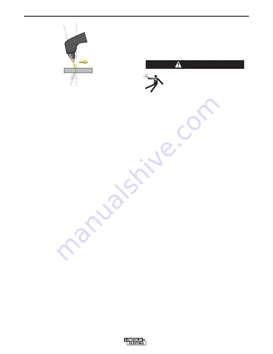
Lincoln Electric Pro-cut 20 Operator'S Manual Download Page 14

Direction of Travel

5

°

 - 15

°

10

°

 - 20

°

Arc Lag

Leading Angle

B-5

OPERATION

B-5

• Use a 5° - 15° leading angle in the direction of the cut.

•  Finish the cut to be made and release the trigger.

• When the trigger is released, the arc will stop.

-  The gas will continue to flow for 10 seconds of

postflow. If the trigger is activated within this time
period, the pilot arc will immediately restart.

• If the dross is difficult to remove, reduce the cutting

speed. High speed dross is more difficult to remove
than low speed dross.

• The right side of the cut is more square than the left

as viewed along the direction of travel. 

• Clean spatter and scale from the nozzle frequently.

•  If the "SAFETY" LED lights at any time; check the

following:

•  Check the assembly of the torch consumables. If

they are not properly in place, the machine will
not start. 

Make sure that the shield cup is hand

tight. Do not use pliers or over tighten.

•  Check the conditions of the inside of the nozzle. If

debris has collected, rub the electrode on the
inside bottom of the nozzle to remove any oxide
layer that may have built up. Refer to
"Suggestions for Extra Utility from the PRO-CUT
system".

•  Check the condition of the electrode. If the end

has a crater-like appearance, replace it along with
the nozzle. The maximum wear depth of the elec-
trode is approximately .062”. A green and erratic
arc will indicate definite electrode failure and the
electrode should be replaced immediately.

•  Replace the nozzle when the orifice exit is eroded

away or oval shaped.

•  After the problem is found, or if there is nothing

apparently wrong, reset the machine by turning the
power switch OFF and then ON again.  (It is possi-
ble for electrical noise to trip the safety circuit on
rare occasions. This should not be a regular occur-
rence.)

•  If the machine does not reset or continues to trip,

consult the Troubleshooting Section.

• Use the  proper cutting procedures referred to in

Procedure Recommendations.

PILOT ARC DISCUSSION

The PRO-CUT has a smooth, continuous pilot arc.
The pilot arc is only a means of transferring the arc to
the workpiece for cutting.  Repeated pilot arc starts, in
rapid succession, is not recommended as these starts
will generally reduce consumable life. Occasionally,
the pilot arc may sputter or start intermittently. This is
aggravated when the consumables are worn or the air
pressure is too high.  Always keep in mind that the
pilot arc is designed to transfer the arc to the work-
piece and not for numerous starts without cutting.

When the pilot arc is started, a slight impulse will be
felt in the torch handle. This occurrence is normal and
is the mechanism which starts the plasma arc. This
impulse can also be used to help troubleshoot a "no
start" condition.

PRO-CUT 20

ELECTRIC SHOCK CAN KILL. 

•  Turn off machine at the disconnect

switch on the front of the machine
before tightening, cleaning or replacing
consumables.

----------------------------------------------------------------------------

WARNING

Summary of Contents for Pro-cut 20

Page 1: ...CONTAINED THROUGHOUT And most importantly think before you act and be careful For use with machines having Code Number 10464 Sales and Service through Subsidiaries and Distributors Worldwide Clevelan...

Page 2: ...ter or metal ELECTRIC SHOCK can kill 1 a The electrode and work or ground circuits are electrically hot when the power source is on Do not touch these hot parts with your bare skin or wet clothing Wea...

Page 3: ...Electric and Magnetic Fields EMF Cutting or gouging current cre ates EMF fields around torch cables and cutting machines 8 b EMF fields may interfere with some pacemakers so opera tors having a pacema...

Page 4: ...ri s et non inflammables 4 Des gouttes de laitier en fusion sont mises de l arc de soudage Se prot ger avec des v tements de protection libres de l huile tels que les gants en cuir chemise paisse pan...

Page 5: ...e information must be followed to avoid minor personal injury or damage to this equipment CAUTION Please Examine Carton and Equipment For Damage Immediately When this equipment is shipped title passes...

Page 6: ...res and Advantages B 2 Cutting Capability B 3 Consumable Life B 3 Limitations B 4 Controls and Settings B 4 Pilot Arc Discussion B 5 Procedure Recommendations B 6 General B 6 Thin Gauge Sheet and Mate...

Page 7: ...1 115 1 230 Fuse Super Lag Circuit Breaker Delay Type 20 AMPS 20 AMPS 14 3 2mm2 14 3 2mm2 2 Input Supply Wires 1 Ground Wire 14 3 2mm2 14 3 2mm2 Type 75o C Copper Wire in Conduit AWG IEC Sizes Depth 1...

Page 8: ...may be used in an environment where other high frequency generat ing machines are operating By taking the following steps high frequency interference into the Pro Cut can be minimized 1 Make sure the...

Page 9: ...ns may overvoltage the Pro Cut 20 power source GAS INPUT CONNECTIONS Supply the PRO CUT 20 with clean compressed air or nitrogen Supply pressure must be between 80 psi and 150 psi Flow rate should be...

Page 10: ...steels and heat treated aluminum for crack resistance and hardness control Job conditions pre vailing codes alloy level and other considerations may also require preheat temperature control The follow...

Page 11: ...ges will help you understand the machine s total capabilities so that you can get maximum use from your machine Light weight and portable design for industrial use Continuous control 12 20 amps Reliab...

Page 12: ...y Chart Recommended Torch Travel Speed IPM 80 of Maximum Speed 100 80 60 40 20 0 0 062 0 125 0 187 0 250 Material Thickness 20 A Thick Line Aluminum Thin Line Mild Steel Figure B 1 CONSUMABLE LIFE The...

Page 13: ...ay show an increase in pressure after the air turns off but this is normal Do NOT reset the pressure while the air is NOT flowing When ready to cut place the torch near the work make certain all safet...

Page 14: ...ill indicate definite electrode failure and the electrode should be replaced immediately Replace the nozzle when the orifice exit is eroded away or oval shaped After the problem is found or if there i...

Page 15: ...turn on the power and continue cutting If the safety circuit continues to trip after cleaning the consumables then replace them with a new set Do not continue to try and cut with excessively worn con...

Page 16: ...or can match its performance GENERAL OPTIONS ACCESSORIES The following options accessories are available for your PRO CUT 20 from your local Lincoln Distributor S22147 028 VORTECH nozzle with an 028 0...

Page 17: ...internal breakdown in the power unit In this case take the unit to an authorized Lincoln Field Service Shop ELECTRIC SHOCK can kill Have an electrician install and service this equipment Turn the inp...

Page 18: ...tom Step 3 RECOMMENDED COURSE OF ACTION This column provides a course of action for the Possible Cause generally it states to contact you local Lincoln Authorized Field Service Facility If you do not...

Page 19: ...tes The safety light does not go out 1 Check the input power to be sure it is on 2 Check the power line fuses and machine connection 3 Disconnect input power at fuse panel and check line switch conti...

Page 20: ...a Reconnect Board may be faulty b The main gas solenoid assem bly may be faulty Check or replace c Possible faulty Control board 2 Remove the handles or barrel of the torch and examine all the con nec...

Page 21: ...the air pressure is set at 65 psi 3 Make sure there are no kinks or restrictions for air flow in the torch cable Replace cable as needed 4 If a slight thump cannot be felt in the torch when the trigg...

Page 22: ...TS S RECOMMENDED COURSE OF ACTION Pilot arc starts but will not transfer when brought near work 1 Check work lead connection for clean secure connection 2 Plasma will only cut conductive material Do n...

Page 23: ...Possible faulty Pressure Switch 4 Possible faulty Control board 1 Turn the power OFF and then ON If torch and consumables are properly installed the Safety LED should turn off Normal cutting or gougi...

Page 24: ...be accurate for all machines covered by this manual The specific diagram for a particular code is pasted inside the machine on one of the enclosure panels If the diagram is illegible write to the Serv...

Page 25: ...6 383 2259 and ask for the Welding School Registrar Lincoln Welding School BASIC COURSE 700 00 5 weeks of fundamentals There is a 10 discount on all orders of 50 00 or more for shipment at one time to...

Page 26: ...electrically live parts or electrode with skin or wet clothing Insulate yourself from work and ground No toque las partes o los electrodos bajo carga con la piel o ropa moja da Aislese del trabajo y...

Page 27: ...e Be und Entl ftung des Arbeitsplatzes Mantenha seu rosto da fuma a Use ventila o e exhaust o para remover fumo da zona respirat ria Turn power off before servicing Desconectar el cable de ali mentaci...

Page 28: ...and Service through Subsidiaries and Distributors Worldwide Cleveland Ohio 44117 1199 U S A TEL 216 481 8100 FAX 216 486 1751 WEB SITE www lincolnelectric com World s Leader in Welding and Cutting Pr...

Reviews: