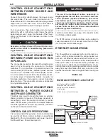
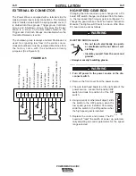
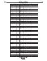
Lincoln Electric POWER WAVE AC/DC Operator'S Manual Download Page 20

A-13

INSTALLATION   

POWER WAVE AC/DC

A-13

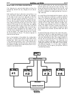
MULTI-ARC SYSTEM DESCRIPTION

The following is a general description of how the
PowerWave AC/DC can be configured in a multi-arc
set-up.

Each welding arc may be driven by one machine or up
to four machines connected in parallel. The hardware
for the power source has been designed so that the
power source can either operate as a master or a
slave. A few DIP switches must be configured proper-
ly to set the machine

s identity. Each power source

has a rating of 500 amps average current, with a peak
current of 725 amps. So, four machines are capable
of driving 2000 amps of output current with up to 2900
amps of peak current available. Each arc must have
one power source designated as the master. If only
one machine is required for an arc, then it must be set
up as the master. The master power source controls
the AC switching for the arc. The slaves respond to
what the master wants

Due to the flexibility of the platform the configuration
may vary. A typical subarc system will consist of four
welding arcs, which require ten power sources and
one synchronous generator. Arc # 1 & #2 will be three
machines in parallel. Arc #3 & #4 will be two machines
connected in parallel (each individual machine is con-
nected to the ethernet hub).

The PC will function as the control center for the
AC/DC system as well as the user interface. The
Ethernet hub splits the Ethernet port from the PC to all
the power sources and the phase generator. The PC
will act to coordinate the welding sequence of the mul-
tiple machines. 

One machine will be designated the master, with the
rest of the machines connected in parallel considered
slaves. The master can generate it's own AC frequen-
cy or it can use an external signal as a reference. An
external Phase Generator provides the means to syn-
chronize the AC wave shape between multiple arcs.
The phase angle between arcs can be adjusted to
reduce "Arc Blow" and other welding related issues.
An external phase control signal is required to keep
the separate wave shapes synchronized with each
other

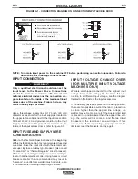
An Ethernet-Gateway board can be used as the exter-
nal Phase Generator. An Ethernet-Gateway PC board
that can be configured to generate four phase signals
onto four differential I/O lines. The phase signals can
then be used to synchronize the four different arcs to
a common carrier frequency. The frequency can
range from 10 hertz to 300 hertz, with the most practi-
cal range being from 50 to 100 hertz. It may be desir-
able that sync signals 2, 3, or 4 are some multiple of
the first signal. The frequency and phase shift are
controlled by software.

Ethernet Hub

PC

ARC

#1

ARC

#2 

ARC

#3

ARC

#4

PULSE

GENERATOR

Summary of Contents for POWER WAVE AC/DC

Page 1: ...WITHOUT READING THIS MANUAL AND THE SAFETY PRECAUTIONS CONTAINED THROUGHOUT And most importantly think before you act and be careful For use with machines having Code Numbers 10849 Date of Purchase S...

Page 2: ...SHOULD CONSULT WITH THEIR DOCTOR BEFORE OPERATING Read and understand the following safety highlights For additional safety information it is strongly recommended that you purchase a copy of Safety in...

Page 3: ...h ground 3 f Maintain the electrode holder work clamp welding cable and welding machine in good safe operating condition Replace damaged insulation 3 g Never dip the electrode in water for cooling 3 h...

Page 4: ...welding sparks from starting a fire Remember that welding sparks and hot materials from welding can easily go through small cracks and openings to adjacent areas Avoid welding near hydraulic lines Hav...

Page 5: ...n inflammables 4 Des gouttes de laitier en fusion sont mises de l arc de soudage Se prot ger avec des v tements de protection libres de l huile tels que les gants en cuir chemise paisse pan talons san...

Page 6: ...e information must be followed to avoid minor personal injury or damage to this equipment CAUTION Please Examine Carton and Equipment For Damage Immediately When this equipment is shipped title passes...

Page 7: ..._________________________ Operation Section B Safety Precautions B 1 Graphic Symbols that appear on this machine or in this manual B 2 Definiition of Welding Terms B 3 General Description B 4 Recommen...

Page 8: ...WIRE IN CONDUIT AWG IEC SIZES MM2 10 6 10 6 10 6 TYPE 75 C COPPER WIRE IN CONDUIT AWG IEC SIZES MM2 8 10 8 10 10 6 PROCESS CURRENT RANGES AC or DC SAW MIG MAG FCAW Pulse CURRENT 50 500 Average Amps 4...

Page 9: ...system at the disconnect switch or fuse box before working on the equipment Do not touch electrically hot parts Always connect the Power Wave grounding lug located inside the reconnect input access do...

Page 10: ...r circuit breakers smaller than recommended may result in nuisance shut offs from welder inrush currents even if the machine is not being used at high currents INPUT VOLTAGE CHANGE OVER FOR MULTIPLE I...

Page 11: ...f the weld current For addi tional information on work voltage sense leads see sections entitled Voltage Sensing and Multiple Unsynchronized Arc Sense Lead and Work Lead Placement Guidelines TWO POWER...

Page 12: ...s sense lead 2 Current flow from Arc 2 affects sense lead 1 Neither sense lead picks up the correct work voltage causing starting and welding arc instability BAD Sense 1 is only affected by weld curre...

Page 13: ...e makes tight metal to metal electrical contact The electrode cable should be sized according to the specifications given in Table A 1 Suggested Copper Cable Sizes 100 Duty Cycle Combined Length of El...

Page 14: ...studs Voltage sense at studs SAW 67 lead required 21 lead optional The electrode voltage 67 sense lead is part of the control cable to the wire feeder For consistent weld quality work voltage sensing...

Page 15: ...LE SPECIFICATIONS It is recommended that genuine Lincoln control cables be used at all times Lincoln cables are specifically designed for the communication and power needs of the Power Wave Power Feed...

Page 16: ...FIGURE A 5 HIGH SPEED GEAR BOX Changing the ratio requires a gear change and a PC board DIP switch change As shipped from the facto ry the low speed high torque gear is configured To change the gear r...

Page 17: ...A 3 default FEED HEAD BOARD DIP SWITCH Switch Description Comments 1 Object Instance LSB see table A 3 2 Object Instance MSB see table A 3 3 Equipment Group 1 Select 4 Equipment Group 2 Select Used f...

Page 18: ...0 21 0 1 0 1 0 1 22 0 1 0 1 1 0 23 0 1 0 1 1 1 24 0 1 1 0 0 0 25 0 1 1 0 0 1 26 0 1 1 0 1 0 27 0 1 1 0 1 1 28 0 1 1 1 0 0 29 0 1 1 1 0 1 30 0 1 1 1 1 0 31 0 1 1 1 1 1 32 1 0 0 0 0 0 33 1 0 0 0 0 1 34...

Page 19: ...A 12 INSTALLATION POWER WAVE AC DC A 12 Bank S3 and S4...

Page 20: ...is con nected to the ethernet hub The PC will function as the control center for the AC DC system as well as the user interface The Ethernet hub splits the Ethernet port from the PC to all the power s...

Page 21: ...ceases Do not touch electrically live parts or electrodes with your skin or wet clothing Insulate yourself from the work and ground Always wear dry insulating gloves FUMES AND GASES can be dan gerous...

Page 22: ...WIRE FEEDER POSITIVE OUTPUT NEGATIVE OUTPUT 3 PHASE INVERTER INPUT POWER THREE PHASE DIRECT CURRENT GMAW FCAW GTAW OPEN CIRCUIT VOLTAGE INPUT VOLTAGE OUTPUT VOLTAGE INPUT CURRENT OUTPUT CURRENT PROTEC...

Page 23: ...of single knob control The machine will select the cor rect voltage and amperage based on the wire feed speed WFS set by the operator WFS Wire Feed Speed CC Constant Current CV Constant Voltage GMAW...

Page 24: ...pin to 14 pin 18 in K1804 2 DUTY CYCLE AND TIME PERIOD The Power Wave AC DC is capable of welding at a 100 duty cycle continuous welding B 4 OPERATION B 4 GENERAL DESCRIPTION The Power Wave AC DC powe...

Page 25: ...ubleshooting Section Not applicable Not applicable 6 LEAD CONNECTOR S2 SENSE LEAD 7 5 PIN ARC LINK S1 8 5 PIN DEVICENET CONNECTOR S5 9 I O CONNECTOR 10 NEGATIVE STUD 11 INTERFACE CONNECTOR S6 12 POSIT...

Page 26: ...controlling all other variables The user adjusts WFS according to factors such as weld size penetration requirements heat input etc The Power Wave then uses the WFS setting to adjust its output charac...

Page 27: ...CV This type of CV mode behaves more like a conven tional CV power source Voltage and WFS are inde pendent adjustments Therefore to maintain the arc characteristics the operator must adjust the volta...

Page 28: ...eform parameters to maintain similar arc properties POWER WAVE AC DC Wave Control 0 0 Wave Control 10 0 Wave Control 10 0 The Power Wave utilizes adaptive control to com pensate for changes in electri...

Page 29: ...tic Applications Control Cables for use on FANUC robot arm 22 pin to 14 pin 10 ft K1804 1 Control Cables for use on FANUC robot arm 14 pin to 22 pin 18 in K1805 1 Control Cables for use on FANUC robot...

Page 30: ...will not need adjustment However neglected or improperly calibrated machines may not yield sat isfactory weld performance To ensure optimal performance the calibration of output Voltage and Current sh...

Page 31: ...BLE CAUSE lists the obvious external possibilities that may contribute to the machine symptom Step 3 RECOMMENDED COURSE OF ACTION This column provides a course of action for the Possible Cause general...

Page 32: ...ield Service facility for technical assistance 1 Make certain that fuses or breakers are properly sized See Installation section of this manual for recommended fuse and breaker sizes 2 Welding procedu...

Page 33: ...s or for excessive dirt clogging coo ing channels in machine 2 DC Bus PC board thermostat has opened check for excessive load on 40VDC supply 3 Be sure process does not exceed duty cycle limit of the...

Page 34: ...procedure Auxiliary receptacle is dead no auxiliary voltage The Power Wave is triggered to weld but there is no output 1 Secondary current limit has been exceeded and the machine has phased back to pr...

Page 35: ...The power source may require calibration Check the current calibration Check the voltage calibration Check the WFS calibration 1 Check for fault signals from the I O connector Possible faults are lac...

Page 36: ...rt Steady Green Blinking Green Alternating Green and Red Steady Red Blinking Red System OK Power source communicating normally with wire feeder and its components Occurs during a reset and indicates t...

Page 37: ...n capacitors May be caused by improper input configuration or an open short circuit in the primary side of the machine Excess voltage on the main capacitors May be caused by improper input configurati...

Page 38: ...266 268 TO J40 J50 J60 67 TO J43 J82 S5 S6 S7 GND A GND B 267 266 268A 893 894 67 S1 S6 227 227 C3 TO AUX 1 N P R S T U V W X A B C D E F G H I J K L M 841 844 842 843 845 846 847 67B 539 541 521 522...

Page 39: ...INPUT S12 MASTER SLAVE OUTPUT S13 717 212A 216A 714 713 213A 716 282A 281A 285B 286A 715 711 718 717 712 714 713 716 715 715A 716A 713A 714A 722A 718A 717A 716A 715A S8 POWER RECEPTACLE 3 1 2 5 6 7 8...

Page 40: ...Tach common Reserved for future use Reserved for future use C Tach 1A differential signal Sync In Reserved for future use D Tach 1B differential signal Sync In Reserved for future use E Tach 2A diffe...

Page 41: ...User supplied electrode lead POWERWAVE CONTROL CABLE K1805 1 WORK SENSE LEAD K940 DEVICENET CABLE K1804 1 CONTROL CABLE OR K1804 2 AND ANY K1795 CONTROL CABLE User supplied work lead User supplied el...

Page 42: ...F 5 DIMENSION PRINT F 5 POWER WAVE AC DC XA 9 45 19 16 19 83 14 62 37 46 18 80 33 08 65 96 34 96 L11656...

Page 43: ...NOTES POWER WAVE AC DC...

Page 44: ...NOTES POWER WAVE AC DC...

Page 45: ...6 383 2259 and ask for the Welding School Registrar Lincoln Welding School BASIC COURSE 700 00 5 weeks of fundamentals There is a 10 discount on all orders of 50 00 or more for shipment at one time to...

Page 46: ...electrically live parts or electrode with skin or wet clothing Insulate yourself from work and ground No toque las partes o los electrodos bajo carga con la piel o ropa moja da Aislese del trabajo y...

Page 47: ...e Be und Entl ftung des Arbeitsplatzes Mantenha seu rosto da fuma a Use ventila o e exhaust o para remover fumo da zona respirat ria Turn power off before servicing Desconectar el cable de ali mentaci...

Page 48: ...and Service through Subsidiaries and Distributors Worldwide Cleveland Ohio 44117 1199 U S A TEL 216 481 8100 FAX 216 486 1751 WEB SITE www lincolnelectric com World s Leader in Welding and Cutting Pr...

Reviews: