Lincoln Electric Power MIG 255C Service Manual Download Page 86

F-46

TROUBLESHOOTING AND REPAIR

F-46

POWER MIG 255C

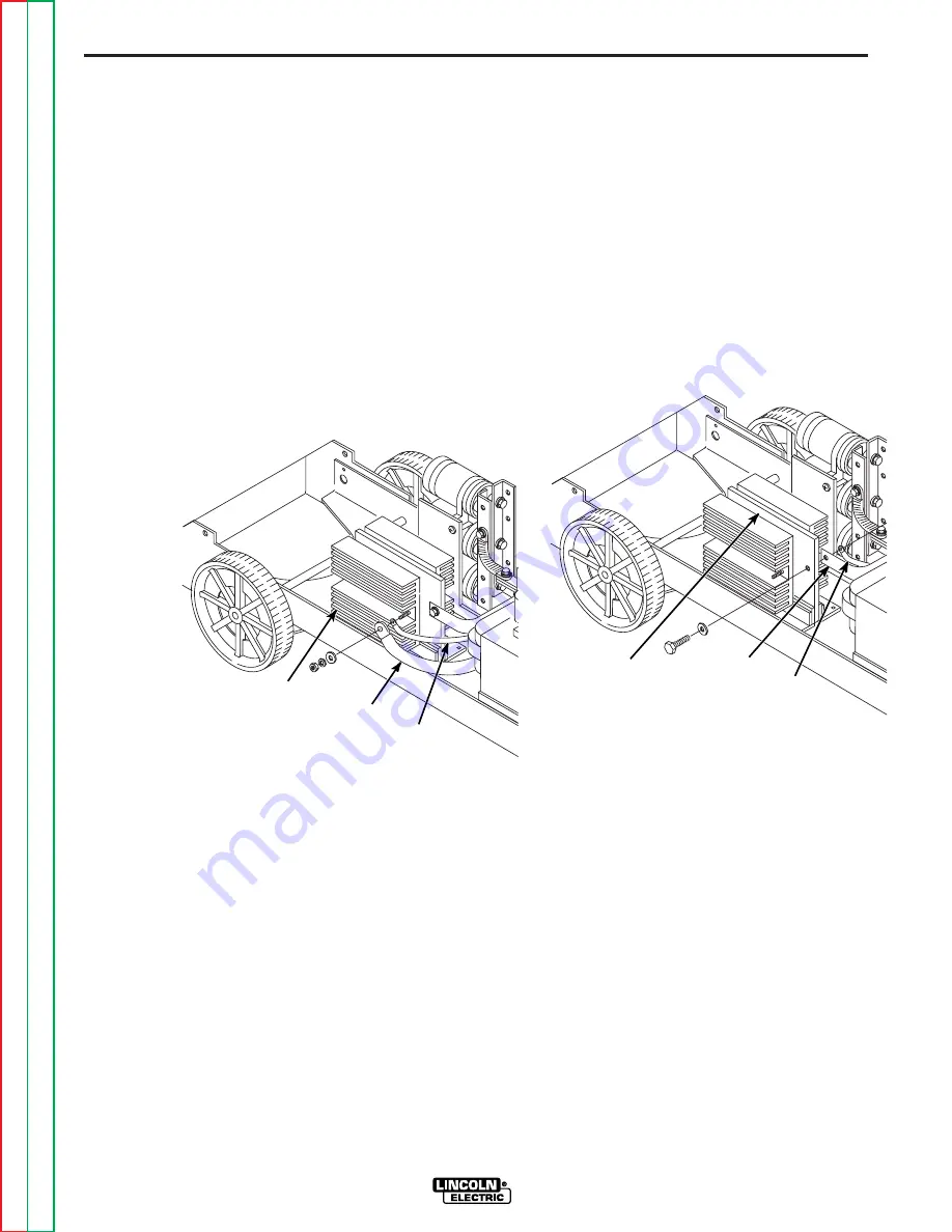
3. Disconnect lead #204 and heavy alu-

minum choke lead from the middle heat
sink with a 1/2 in. socket wrench and
1/2 in. open end wrench.  See Figure
F.14.

4. Remove the diode lead from the nega-

tive capacitor band buss bar on the
right side of the machine using a 1/2 in.
socket and 3/8 in. open end wrench.

FIGURE F.14 — MIDDLE  HEAT  SINK

LEAD  DISCONNECTION.

PROCEDURE

1. Remove the case side panels using a

3/8 in. nutdriver.

2.  Disconnect lead #208S and trans-

former lead X1 from the heat sink on
the left side of the machine using a 1/2
in. socket wrench. See Figure F.13.

a. Thin lead is always on the outboard

side of the connection.

FIGURE F.13 — LEFT  HEAT  SINK

LEAD  DISCONNECTION.

SCR  OUTPUT  RECTIFIER  REMOVAL AND  REPLACEMENT  (continued)

LEAD X1

LEAD

#208S

LEFT

HEAT SINK

HEAVY

LEAD

LEAD

#204S

MIDDLE

HEAT  SINK

Retur

n to Section TOC

Retur

n to Section TOC

Retur

n to Section TOC

Retur

n to Section TOC

Retur

n to Master TOC

Retur

n to Master TOC

Retur

n to Master TOC

Retur

n to Master TOC

Summary of Contents for Power MIG 255C

Page 1: ...ONS CON TAINED THROUGHOUT And most importantly think before you act and be careful SERVICE MANUAL For use with machines having Code Number 11192 11218 Return to Master TOC Return to Master TOC Return...

Page 2: ...NJURY OR DEATH KEEP CHILDREN AWAY PACEMAKER WEARERS SHOULD CONSULT WITH THEIR DOCTOR BEFORE OPERATING Read and understand the following safety highlights For additional safety information it is strong...

Page 3: ...ver dip the electrode in water for cooling 3 h Never simultaneously touch electrically hot parts of electrode holders connected to two welders because voltage between the two can be the total of the o...

Page 4: ...possible cover them to prevent the welding sparks from starting a fire Remember that welding sparks and hot materials from welding can easily go through small cracks and openings to adjacent areas Av...

Page 5: ...soudage l aide d crans appropri s et non inflammables 4 Des gouttes de laitier en fusion sont mises de l arc de soudage Se prot ger avec des v tements de protection libres de l huile tels que les gant...

Page 6: ...NTS FOR ALL SECTIONS Page Safety i iv Installation Section A Operation Section B Accessories Section C Maintenance Section D Theory of Operation Section E Troubleshooting and Repair Section F Electric...

Page 7: ...crating the POWER MIG 255C A 3 Location A 3 Input Power Grounding and Connection Diagrams A 3 Dual Voltage Machine Input Connections A 4 Triple Voltage Machine Input Connections A 5 Output Polarity Co...

Page 8: ...SE SIZES Height Width Depth Weight 31 79 in 18 88 in 38 78 in 220 Ibs 808 mm 480 mm 985 mm 100 kg PHYSICAL DIMENSIONS Wire Speed 50 700 IPM 1 27 17 8 m minute WIRE SPEED RANGE Standard Voltage Frequen...

Page 9: ...t have read and under stood the POWER MIG 255C Operating Manual should install and operate this equip ment Machine must be grounded per any national local or other applicable electrical codes The POWE...

Page 10: ...the welder frame when the welder plug is inserted into the receptacle 3 The 208 230 volt 60 Hz model POWER MIG is shipped with a 10 ft input cable and plug con nected to the welder A matching receptac...

Page 11: ...larity This is the normal polarity for GMA welding If negative polarity is required interchange the con nection of the two cables located in the wire drive com partment near the front panel The electr...

Page 12: ...away from the outlet and open the cylinder valve for an instant This blows away any dust or dirt which may have accumulated in the valve outlet Be sure to keep your face away from the valve out let wh...

Page 13: ...Spools 12 in 300 mm Diameter or 14 lb 6 kg Innershield Coils B 5 To Start the Welder B 6 Feeding Wire Electrode B 6 Idle Roll Pressure Setting B 6 Wire Drive Configuration B 6 B 7 Setting Run In Speed...

Page 14: ...rous Keep your head out of fumes Use ventilation or exhaust to remove fumes from breathing zone WELDING SPARKS can cause fire or explosion Keep flammable material away Do not weld on closed containers...

Page 15: ...e Run In for wire starting optimization Also optional are a Dual Cylinder Mounting kit and an Aluminum Feeding Kit for push feeding with standard built in feeder RECOMMENDED PROCESSES AND EQUIPMENT Th...

Page 16: ...OWER MIG 255C have two grooves one for 035 0 9mm wire Solid Steel electrode and the other for 045 1 2mm wire Drive roll size is stenciled on each side of the drive roll If feed ing problems occur chec...

Page 17: ...rotate in a direction when feeding so as to be de reeled from top of the coil 7 Set one of the Readi Reel inside cage wires on the slot in the retaining spring tab 8 Lower the Readi Reel to depress th...

Page 18: ...r OFF at the welding power source before installation or changing drive rolls and or guides Do not touch electrically live parts When inching with the gun trigger electrode and drive mechanism are hot...

Page 19: ...d plate Slide the gun receiver bushing into the wire drive and verify the thumb screw holes are aligned 10 Tighten the socket head cap screw 11 Insert the welding gun into the gun bushing and tighten...

Page 20: ...de MAKING A WELD 1 Check that the electrode polarity is correct for the process being used then turn the power switch ON 2 Set desired arc voltage and wire speed for the particular electrode wire mate...

Page 21: ...er drive rolls and wire drive idle roll pressure for wire size and type being used FAN CONTROL The fan is designed to come on automatically when a weld arc is established The fan will stay on for a mi...

Page 22: ...ECTION The machine will automatically reduce the output if the load on the machine exceeds 300 to 320 amperes This protects the welding power SCR s from excessive short circuit currents and from excee...

Page 23: ...Adapter C 2 Dual Cylinder Mounting Kit K1702 1 C 2 Alternative Magnum GMAW Gun and Cable Assemblies C 2 Magnum Gun Connection Kit Optional K466 6 C 2 Timer Kit Installation Optional K1701 1 C 2 Operat...

Page 24: ...es TIMER KIT INSTALLATION Optional K1701 1 The timer kit adds selectable 4 step trigger interlock spot and Run In functions and manual adjustment of burnback time Install as follows or per the instruc...

Page 25: ...icking in the puddle after each weld Too long of a burnback time may form a ball on the end of the wire or may flash back to the gun tip E Run In Mode is used to adjust the starting wire feed speed St...

Page 26: ...IG 255C input power ON b Adjusting the voltage control will increase or decrease your welding voltage CAUTION K2445 1 CABLE ADAPTER 7 pin to 6 pin Note This adapter is only for The Magnum SG Spool Gun...

Page 27: ...speed control on the spool gun will increase or decrease the spool gun wire feed speed d For the Magnum SG Spool Gun the wire feed speed is controlled by combination of the wire feed speed displayed...

Page 28: ...C 6 NOTES POWER MIG 255 C 6 Return to Section TOC Return to Section TOC Return to Section TOC Return to Section TOC Return to Master TOC Return to Master TOC Return to Master TOC Return to Master TOC...

Page 29: ...ates D 2 Contact Tip Gas Nozzle Installation D 2 Gun Tubes and Nozzles D 2 Gun Cable Cleaning D 2 Liner Removal and Replacement D 2 Liner Removal Installation and Trimming Instructions for Magnum 250L...

Page 30: ...s see Table D 2 in this section WARNING 1 Be sure the nozzle insulator is fully screwed onto the gun tube and does not block the gas holes in the dif fuser 2 Slip the appropriate gas nozzle onto the n...

Page 31: ...ra ajustable Electrodos Utilizados Gu a CilindrodelaGu a grabado grabado 025 030 Steel KP1934 2 030 0 8 mm KP2026 3 KP2026 2 0 6 0 8 mm 035 045 Steel KP1934 1 045 1 2 mm KP2026 3 KP2026 1B1 0 9 1 2 mm...

Page 32: ...2020 2B1 045 1 2 mm Heavy Duty KP2021 1B1 035 0 9 mm KP2021 2B1 045 1 2 mm Tapered KP2021 5B1 025 0 6 mm KP2021 6B1 030 0 8 mm KP2022 1B1 035 0 9 mm KP2022 2B1 045 1 2 mm Notched For Alum KP2010 5B1 3...

Page 33: ...rload Protection E 6 Overcurrent Protection E 6 Wire Feed Overload Protection E 6 SCR Operation E 7 FIGURE E 1 BLOCK LOGIC DIAGRAM Return to Master TOC Return to Master TOC Return to Master TOC Return...

Page 34: ...115 VAC 30 VAC G A T E S I G N A L SCR RECTIFIER POWER ENHANCEMENT CHOKE OUTPUT CHOKE C A P A C I T O R S F E E D B A C K NEGATIVE TERMINAL POSITIVE TERMINAL SHUNT SPOOL GUN AUX gate drive circuitry...

Page 35: ...30 VAC G A T E S I G N A L SCR RECTIFIER POWER ENHANCEMENT CHOKE OUTPUT CHOKE C A P A C I T O R S F E E D B A C K NEGATIVE TERMINAL POSITIVE TERMINAL SHUNT SPOOL GUN AUX FIGURE E 3 OUTPUT RECTIFICATI...

Page 36: ...OTOR CONTROL BOARD WIRE DRIVE MOTOR TACH GUN TRIGGER FEEDBACK 115 VAC 30 VAC G A T E S I G N A L SCR RECTIFIER POWER ENHANCEMENT CHOKE OUTPUT CHOKE C A P A C I T O R S F E E D B A C K NEGATIVE TERMINA...

Page 37: ...ARC VOLTAGE WIRE SPEED GAS SOLENOID FAN MOTOR CONTROL BOARD WIRE DRIVE MOTOR TACH GUN TRIGGER FEEDBACK 115 VAC 30 VAC G A T E S I G N A L SCR RECTIFIER POWER ENHANCEMENT CHOKE OUTPUT CHOKE C A P A C I...

Page 38: ...ved and the fan problem or air obstruction be corrected OVERCURRENT PROTECTION The machine will automatically reduce the output if the load on the machine exceeds 300 to 320 amperes This protects the...

Page 39: ...trolled by the gate An SCR is fired by a short burst of current into the gate This gate pulse must be more positive than the cath ode voltage Since there is a standard PN junction between gate and ca...

Page 40: ...E 8 NOTES POWER MIG 255C E 8 Return to Section TOC Return to Section TOC Return to Section TOC Return to Section TOC Return to Master TOC Return to Master TOC Return to Master TOC Return to Master TOC...

Page 41: ...aveform F 31 Typical Output Voltage Waveform Machine Loaded F 32 Abnormal Output Voltage Waveform Machine Loaded One Output SCR Not Functioning F 33 Abnormal Open Circuit Voltage Output Capacitor Bank...

Page 42: ...onents in the order listed to eliminate one possibility at a time until you locate the cause of your problem All of the referenced test procedures referred to in the Troubleshooting Guide are describe...

Page 43: ...uipment Do not touch electrically hot parts Remove the PC board from the static shielding bag and place it directly into the equipment Don t set the PC board on or near paper plastic or cloth which co...

Page 44: ...hine s duty cycle is not being exceeded 5 Check the trigger circuit Leads 324 to 325 should have conti nuity zero ohms when the gun trigger is pulled If not then the gun may be faulty replace 6 Make s...

Page 45: ...ndary leads are securely connected to the SCR rectifier assembly 3 Perform the SCR Rectifier Assembly Tests 4 Perform Main Transformer Test 5 The control board may be faulty Replace 1 Check for loose...

Page 46: ...within the POWER MIG 255C Contact your local Lincoln Electric Authorized Field Service Facility 1 Check the machine s internal trigger leads for grounds or shorts See Wiring Diagram 2 The control boa...

Page 47: ...Wiring Diagram 2 Perform the SCR Rectifier Assembly Tests 3 The control board may be faulty Replace 1 Check the gas solenoid by dis connecting it from the control board Plug J8 and applying a 12 VDC e...

Page 48: ...contact your local Lincoln Electric Authorized Field Service Facility 1 The Wire Speed Control poten tiometer may be faulty Check or replace See Wiring Diagram 2 Perform the Wire Drive Motor and Tach...

Page 49: ...ure shielding gas is cor rect and flow is proper 3 Make sure the weld joint is not contaminated 1 Check for loose connections at the output terminals the chokes the capacitor bank and all heavy curren...

Page 50: ...nections 2 Make sure the wire feed speed voltage and shielding gas are correct for the process being used 1 Make sure tip is tight in diffuser 1 Perform the SCR Rectifier Assembly Tests 2 The control...

Page 51: ...procedures or are unable to per form the test repairs safely contact the Lincoln Electric service department for technical troubleshooting assistance before you proceed Call 1 888 935 3877 TEST DESCR...

Page 52: ...connect the main input power sup ply to the machine 2 Remove the case top and side panels with a 3 8 in nutdriver 3 Remove the tool tray with a 5 16 in nut driver FIGURE F 1 G3521 CONTROL PC BOARD AND...

Page 53: ...255C ON OFF POWER SWITCH to ON 8 Carefully make the following voltage tests at plug J6 a Turn the machine OFF between each test b Carefully insert the meter probes into the back of each Molex plug pi...

Page 54: ...are missing or are incorrect the main transformer may be faulty Replace 14 Locate the following leads on plug J5 on the Control PC board See Figure F 1 15 Turn the machine ON 16 Make the following vo...

Page 55: ...e test procedures or are unable to per form the test repairs safely contact the Lincoln Electric service department for technical troubleshooting assistance before you proceed Call 1 888 935 3877 TEST...

Page 56: ...Remove the case top and side panels with a 3 8 in nutdriver 3 Perform the Main Transformer Test to ensure the proper voltages are supplied to the J5 plug on the Control board 4 Locate the following l...

Page 57: ...ing voltage tests a Turn the machine OFF between each test b Carefully connect the meter plugs to the exposed lead connections c Turn the machine ON to conduct the voltage test at J5 connector Control...

Page 58: ...18 NOTES POWER MIG 255C F 18 Return to Section TOC Return to Section TOC Return to Section TOC Return to Section TOC Return to Master TOC Return to Master TOC Return to Master TOC Return to Master TO...

Page 59: ...form the test repairs safely contact the Lincoln Electric service department for technical troubleshooting assistance before you proceed Call 1 888 935 3877 TEST DESCRIPTION This test is used to quic...

Page 60: ...connect main AC input power to the machine 2 Remove the case top and side panels with a 3 8 in nutdriver 3 Remove the tool tray with a 5 16 in nut driver STATIC SCR RECTIFIER ASSEMBLY TEST continued F...

Page 61: ...R go to the Active SCR Rectifier Assembly Test FIGURE F 4 LOCATION OF LEADS X2 AND X3 6 Disconnect leads X2 and X3 braided copper strap from the negative capaci tor bank buss bar using a 1 2 in open e...

Page 62: ...22 NOTES POWER MIG 255C F 22 Return to Section TOC Return to Section TOC Return to Section TOC Return to Section TOC Return to Master TOC Return to Master TOC Return to Master TOC Return to Master TO...

Page 63: ...ctric service department for technical troubleshooting assistance before you proceed Call 1 888 935 3877 TEST DESCRIPTION The Active SCR Rectifier Assembly Test will determine if the device is able to...

Page 64: ...nect main AC input power to the machine 2 Remove the case top and side panels with a 3 8 in nutdriver 3 Remove the tool tray with a 5 16 in nut driver ACTIVE SCR RECTIFIER ASSEMBLY TEST continued FIGU...

Page 65: ...EPAIR F 25 POWER MIG 255C 6 Disconnect leads X2 and X3 braided copper strap from the negative capaci tor bank buss bar using a 1 2 in open end wrench See Figure F 7 FIGURE F 7 LOCATION OF LEADS X2 AND...

Page 66: ...d A to the anode b Connect tester lead C to the cathode c Connect tester lead G to the gate 10 Close switch SW 1 NOTE Switch SW 2 should be open 11 Read meter for zero voltage a If the voltage reading...

Page 67: ...throughout this manual If for any reason you do not understand the test procedures or are unable to per form the test repairs safely contact the Lincoln Electric service department for technical trou...

Page 68: ...ut power to the machine 2 Open the side panels and remove the tool tray using a 5 16 in nutdriver FIGURE F 9 PLUG J1 LOCATION ON CONTROL PC BOARD J6 J5 J3 J8 J1 J4 J2 555 6J1 W 2J1 206B 1J1 515B 5J1 B...

Page 69: ...the test c Turn the machine ON and pull the gun trigger to conduct the voltage test 7 If the voltage to the wire drive motor armature is zero check the wires between plug J1 and the wire drive motor A...

Page 70: ...e tool tray TEST FOR FEEDBACK VOLTAGE TO CONTROL BOARD 1 Disconnect the main AC input power to the machine 2 Locate plug J1 on the control PC board 3 Locate the following leads on plug J1 see Figure F...

Page 71: ...al division represents 2 5 milliseconds in time NOTE Scope probes connected at machine output terminals probe to elec trode probe to work Volts Div 20 V Div Horizontal Sweep 2 5 ms Div Coupling DC Tri...

Page 72: ...sents 20 volts and that each horizontal division represents 5 milliseconds in time The machine was loaded with a resistance grid bank NOTE Scope probes connected at machine output terminals probe to e...

Page 73: ...an open or non functioning output SCR Each vertical division represents 20 volts and each horizontal division represents 5 mil liseconds in time The machine was loaded with a resistance grid bank NOT...

Page 74: ...ut capacitor bank was disconnected Each vertical division represents 20 volts and each horizontal divi sion represents 5 milliseconds in time NOTE Scope probes connected at machine output terminals pr...

Page 75: ...vision represents 2 volts and each horizontal division represents 5 milliseconds in time NOTE Scope probes connected at Plug J6 on the control board The probe to lead G2 and the probe to lead 204 Volt...

Page 76: ...36 NOTES POWER MIG 255C F 36 Return to Section TOC Return to Section TOC Return to Section TOC Return to Section TOC Return to Master TOC Return to Master TOC Return to Master TOC Return to Master TO...

Page 77: ...test repairs safely contact the Lincoln Electric service department for technical troubleshooting assistance before you proceed Call 1 888 935 3877 POWER MIG 255C WARNING Printed Circuit Boards can b...

Page 78: ...er 3 Disconnect all wiring harness plugs and Molex plugs connected to the control board See Figure F 10 FIGURE F 10 WIRING HARNESS AND MOLEX PLUG LOCATIONS J1 J2 J3 J4 J5 J6 J8 CONTROL PC BOARD REMOVA...

Page 79: ...before handling the con trol PC boards 5 Carefully remove the control PC board from the mounting standoffs 6 Lift the control PC board straight up and out from the machine FIGURE F 11 CONTROL BOARD M...

Page 80: ...40 NOTES POWER MIG 255C F 40 Return to Section TOC Return to Section TOC Return to Section TOC Return to Section TOC Return to Master TOC Return to Master TOC Return to Master TOC Return to Master TO...

Page 81: ...eason you do not understand the test procedures or are unable to per form the test repairs safely contact the Lincoln Electric service department for technical troubleshooting assistance before you pr...

Page 82: ...s 3A Connection Bar 3B Socket Head Cap Screw 3C Plain Washer 3D Retaining Ring 3E Idle Arm Not Shown 3F Adjustment Arm Assembly 3G Roll Pin Not Shown 3H 1 4 20 x 50 HHCS 3J Lock Washer 3K Plain Washer...

Page 83: ...le the wire drive assembly in the reverse order PROCEDURE 1 Disconnect main input power to the machine 2 Remove the wire gun and wire 3 Lift the wire drive door to gain access to the wire drive assemb...

Page 84: ...44 NOTES POWER MIG 255C F 44 Return to Section TOC Return to Section TOC Return to Section TOC Return to Section TOC Return to Master TOC Return to Master TOC Return to Master TOC Return to Master TO...

Page 85: ...any reason you do not understand the test procedures or are unable to per form the test repairs safely contact the Lincoln Electric service department for technical troubleshooting assistance before y...

Page 86: ...RE 1 Remove the case side panels using a 3 8 in nutdriver 2 Disconnect lead 208S and trans former lead X1 from the heat sink on the left side of the machine using a 1 2 in socket wrench See Figure F 1...

Page 87: ...mer lead X4 from the right side heat sink using a 1 2 in socket wrench and 1 2 in open end wrench See Figure F 15 6 Unplug the SCR gate leads G1 and G2 see wire markers and wiring diagram 7 Remove the...

Page 88: ...48 NOTES POWER MIG 255C F 48 Return to Section TOC Return to Section TOC Return to Section TOC Return to Section TOC Return to Master TOC Return to Master TOC Return to Master TOC Return to Master TO...

Page 89: ...s or are unable to per form the test repairs safely contact the Lincoln Electric service department for technical troubleshooting assistance before you proceed Call 1 888 935 3877 POWER MIG 255C WARNI...

Page 90: ...and replacement components 1 Disconnect main input power to the machine 2 Remove the case side panels using a 3 8 in nutdriver 3 Test that the capacitors are discharged using a volt ohmmeter Polarity...

Page 91: ...derstand the test procedures or are unable to per form the test repairs safely contact the Lincoln Electric service department for technical troubleshooting assistance before you proceed Call 1 888 93...

Page 92: ...that the capacitors are discharged using a volt ohmmeter Polarity must be observed 4 Remove lead X1 from the left side SCR heat sink assembly using a 1 2 in sock et wrench extender and universal adap...

Page 93: ...type that could get in the way during trans former removal using wire cutters and screw driver 14 Remove the four nuts and washers mounting the transformer to the floor of the machine using a 1 2 in w...

Page 94: ...OTES POWER MIG 255C F 54 F 54 Return to Section TOC Return to Section TOC Return to Section TOC Return to Section TOC Return to Master TOC Return to Master TOC Return to Master TOC Return to Master TO...

Page 95: ...t this manual If for any reason you do not understand the test procedures or are unable to per form the test repairs safely contact the Lincoln Electric service department for technical troubleshootin...

Page 96: ...ng compo nents in reverse order of removal PROCEDURE 1 Disconnect main input power to the machine 1 Remove the case side panels using a 3 8 in nutdriver 2 Disconnect the fan motor leads 352 and 352 Se...

Page 97: ...OLTAGE RETEST AFTER REPAIR Maximum Idle Watts Maximum Idle Amps Input Volts Hertz 400 7 0 230 60 50 700 IPM 1 27 17 8 m minute 35 40 VDC Return to Section TOC Return to Section TOC Return to Section T...

Page 98: ...NOTES POWER MIG 255C Return to Section TOC Return to Section TOC Return to Section TOC Return to Section TOC Return to Master TOC Return to Master TOC Return to Master TOC Return to Master TOC...

Page 99: ...ring Diagram Entire Machine Code 11192 L12464 G 2 Wiring Diagram Entire Machine Code 11218 L12506 G 3 Schematic Entire Machine G4752 G 4 Schematic Control PC Board G4823 2D1 Sheet 1 G 5 Schematic Cont...

Page 100: ...may not be accurate for all machines covered by this manual The wiring diagram specific to your code is pasted inside one of the enclosure panels of your machine Return to Section TOC Return to Sectio...

Page 101: ...may not be accurate for all machines covered by this manual The wiring diagram specific to your code is pasted inside one of the enclosure panels of your machine Return to Section TOC Return to Sectio...

Page 102: ...o Section TOC Return to Master TOC Return to Master TOC Return to Master TOC Return to Master TOC ELECTRICAL DIAGRAMS G 4 POWER MIG 255C SCHEMATIC ENTIRE MACHINE G4752 G 4 NOTE This diagram is for ref...

Page 103: ...1 G 5 NOTE This diagram is for reference only It may not be accurate for all machines covered by this manual Return to Section TOC Return to Section TOC Return to Section TOC Return to Section TOC Re...

Page 104: ...2 G 6 NOTE This diagram is for reference only It may not be accurate for all machines covered by this manual Return to Section TOC Return to Section TOC Return to Section TOC Return to Section TOC Re...

Page 105: ...3 G 7 NOTE This diagram is for reference only It may not be accurate for all machines covered by this manual Return to Section TOC Return to Section TOC Return to Section TOC Return to Section TOC Re...

Page 106: ...S19400 6810 RESISTOR MF 1 4W 681 1 R14 R15 R27 R123 4 S19400 15R0 RESISTOR MF 1 4W 15 0 1 R18 R20 R24 R80 4 S19400 5620 RESISTOR MF 1 4W 562 1 R19 R21 R58 R83 R144 R178 R179 R180 RESISTOR MF 1 4W 2 2...

Page 107: ...51 J10 7 VOLTS J10 5 10K R7 50V 0047 C8 X5 10 11 475 R8 50V 0047 C7 X5 8 9 10K R6 10K R5 475 R9 DISP7 2 1 4 9 5 10 7 6 8 3 DISP6 2 1 4 9 5 10 7 6 8 3 500 500 500 14 3 Rx Vdd d BANK1 g DATA OUT f ENABL...

Page 108: ...T DR DATE CHK REF SUP S D G SHT NO L L IDENTIFICATION PART NO REQ D ITEM 49 0 5 80 04 20 0 STANDARD DISPLAY P C BD ASSEMBLY 1 44 1 64 04 5 60 2 90 C1 1 S13490 25 4 7 35 C2 1 S13490 39 18 15 C3 C4 C10...

Page 109: ..._ ___________________________________________________________________________ ___________________________________________________________________________ ______________________________________________...

Reviews: